Robust design for field use.
Precise measurement in a high voltage environment
Both sides grounded (optional)
Built-in micro ohmmeter (up to 500 A)
Dynamic resistance measurement
Detailed analysis of test results with DV-Win software
Database of circuit breaker test plans.
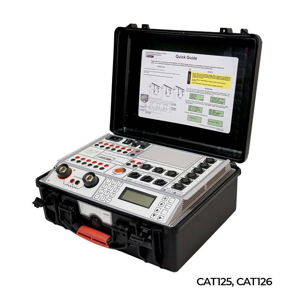
Description The Advanced CAT Series Analyzers and Timers are stand-alone or PC-controlled digital instruments for circuit breaker status evaluation. Timing channels record arc closing and opening, resistance and auxiliary contacts. The main contact channels can also measure the resistance value of pre-insertion resistors (if present in the breaker). The advanced CAT series records graphs of the opening and closing coil currents and the movements of the moving parts of the high and medium voltage circuit breaker. Test results are printed on the 112 mm (4.4 inch) thermal printer (optional accessory) in tabular and graphical form. The advanced CAT series provides easy selection of different operating modes:
Open (O)
Close (C)
Recoil (O-0,3s-C)
Trip free (CO)
O-0,3s-CO
Open-Close (O-C)
Close-Open (C-O)
Open-Close-Open (O-C-O)
First trip (O)
Multiple operations, such as open-closure and open-close-open, can be initiated using the predefined delay time or by detecting the position of the switch contact. The operation of the breaker can be initiated in different ways (e.g. from a control room, by a local breaker or externally by a test device) depending on the test conditions. Measurement triggers, which are used to measure time at various times, are available to record measurements under different test conditions:
external trigger
analog channels
auxiliary channels
Coil control channel The auxiliary inputs are used to control the dry and wet auxiliary contacts.
The six analog coil control channels can simultaneously measure and record coil currents (OPEN and CLOSED), up to 35 A AC/DC. The six additional analog voltage channels have four selectable voltage ranges available (±1 V, ±5 V, ±60 V and ±300 V AC/DC). They are used for monitoring:
Coil resistance measurement (simultaneously for 3 coils - during opening or closing sequence);
Breaker substation battery voltage;
DC and AC currents during the "First trip" test
Other types of analogue signals that may be relevant.
Three transducer channels provide measurement of displacement of moving parts of the breaker, contact friction, overtravel, rebound, damping time and average speed. An analog or digital transducer can be connected to these universal channels.
Application The list of applications of the instrument includes:
Simultaneous time measurement of up to 12 main contacts (4 breaks per phase), including pre-insertion resistors (if present in the breaker) and 6 auxiliary contacts.
Resistance measurement of pre-insertion resistors (if present in the circuit breaker).
Evaluation of synchronization between the breaker's poles.
Measurement of currents, voltages and coil resistance, simultaneously for 6 coils - Evaluation of the substation battery status by graphically displaying the voltage value
Measurement of displacement, contact friction, overtravel, rebound, damping time and the average speed of the moving parts of the switch
The "First trip" test
Static resistance measurement
Dynamic resistance measurement
Time measurement
The timing of mechanical operations is one of the most important tests to determine the actual condition of the breaker. The timing measurement tests meet all the requirements defined by IEC 62271-100 and IEEE C37.09. In three-phase systems, not only do the single-pole contacts have to operate simultaneously, but all poles must also operate at the same time. All contacts must be synchronized, within a certain tolerance limit. The synchronisation between the poles of the circuit breaker during opening shall not exceed 1/6 of the nominal frequency cycle (3.33 ms at 50 Hz; 2.78 ms at 60 Hz) and during closing - 1/4 of the nominal frequency cycle, too (5.0 ms at 50 Hz; 4.17 ms at 60 Hz). Simultaneous measurements within a single phase are important in situations where several contacts are connected in series. The maximum difference between contact separation times within interrupter units connected in series shall not exceed 1/8 of the rated frequency cycle (2.50 ms at 50 Hz; 2.08 ms at 60 Hz). The maximum difference between contact instants within interrupter units connected in series shall not exceed 1/6 of a rated frequency cycle (3.33 ms at 50 Hz; 2.78 ms at 60 Hz). The auxiliary contacts are mechanically driven by the operating mechanism and are used for monitoring and indicating the state of the main contacts. There are no general requirements, related to the timing measurement of auxiliary contacts, described in the IEC® and IEEE® standards. However, in order to evaluate the state of the high-voltage switches, it is important to verify their operation. The "a" type contact follows the position of the main contact of the circuit breaker and must be closed/opened before the main contact is closed/opened. The "a" contact is connected in series with the open coil and interrupts the open coil circuit when the breaker opens. The "b" contact should open/close when the operating mechanism has released its stored energy to close/open the ACB. Contact "b" is connected in series with the closing coil, interrupting the closing coil circuit when the ACB is closed.
Download the catalogue of CAT Advanced Series.
If you want to acquire Switch testing equipment with quality, you can also consult prices of Switch testing equipment.
If you have any doubts or need advice from our engineers, don't hesitate to contact us and we will be pleased to help you. You can also call us at (+34) 982 20 99 20.