Testing and checking of switches
Table of Contents
What you can try
Main Circuit
- Temporization of the operation of the main contacts and PIR contacts
- Contact (static) resistance (SRM)
- Dynamic Resistance Measurement (DRM)
- Testing under BSG conditions
Operating mechanism
- Movement and speed
- Spring mechanism load time and motor current measurement
- Motor current measurement
Auxiliary circuit
- Temporization of the auxiliary contacts operations
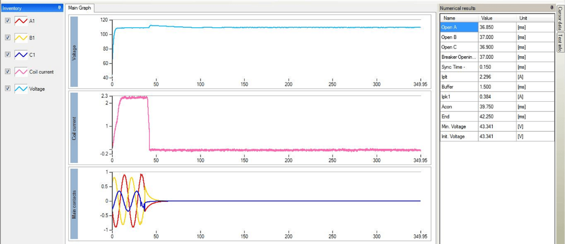
- Waveform of the coil current (resistance)
- Supply voltage measurement
- "First trip" test (in-line test)
- Minimum trip voltage
Types of tests (application)
- Measuring the timing of main, arcing and PIR contacts of circuit breakers (IEC 62271-100)
- Measuring the timing of the main, arcing and PIR contacts of circuit breakers (IEC 62271-100)
- Measuring contact resistance (IEC 62271-1)
- Dynamic measurement of the contact resistance (IEC 62271-1)
- Dynamic measurement of the resistance
- Motion and speed (IEC 62271-100)
- Motor mechanism load time (IEC 62271-100)
- Coil resistance (IEC 62271-100)
- Coil current (IEC 62271-100)
- Minimum tripping current (IEC 62271-100)
- Minimum tripping voltage (IEC56, ANSI C37.09)
- Auxiliary contact timing measurement (IEC 62271-100)
- Minimum trip voltage (IEC56, ANSI C37.09)
- "First trip" test (in-line test)
- Vibration analysis
- Voltage supply for coil and motors
Time measurement
Definitions (IEC 62271-100):
- Opening time - for a circuit-breaker tripped by any form of auxiliary energy, the opening time is the time interval between the instant of energizing of the shunt opening release, the circuit-breaker being in the closed position, and the instant when the arcing contacts have separated in all poles.
Definitions (IEC 62271-100): 3.7.136
- Post simultaneity requirement during single-closing and single-opening operations
Main contact operating time measurement
- Conventional method
(one side connected to ground) - Both sides grounded (BSG) method:
- a) Tank under voltage circuit breaker
- b) Dead tank circuit breakers
- c) GIS circuit breakers
Safety
Both sides grounded on AIS (live tank)
IEEE Standard 510-1983 "IEEE Recommended Practices for High Voltage and High Power Test Safety"
IEEE Standard 510-1983.
Main contact wire connection for BSG for AIS circuit breakers
- BSG - timing in Both Sides Grounded
- conditions.
- The same cables are used as for conventional timing
- Works correctly for a grounding path resistance ≥10 mΩ
Both sides Grounding timing on the dead tank circuit breaker
- The method is based on injecting direct current (a few tens of amperes per phase) through the main circuit and the grounding path and measuring the response signals at the secondary terminals of the current transformer (CT).
Both sides grounded in GIS (gas insulated substation) CB
- The method is based on the injection of high DC current through the grounding and main circuit and the simultaneous recording of the response in the secondary of the current transformers (current or voltage).
Contact resistance (static)
measurement.
- IEC56 (IEC62271-100): 50 A ≤I
- IEEE C 37.09: 100 A ≤I
- Why is high DC current used
The higher the current, the higher the accuracy, contamination and oxidation of the contact surface
According to the standard, a test current as close as possible to the rated current
is recommended.
- Some devices can generate up to 800 A
- Continuous DTR test for stable results on GIS and Dead Tank circuit breakers
Both sides grounded
- Why
Safety reasons
- How?
Current clamp
Dynamic resistance measurement
- The DRM test is performed by injecting a high current through the breaker contact and simultaneously monitoring the voltage drop across the breaker contact during operation.
- DRM on Open, Close, CO, O-CO, and O-CO operations!
- Important for arcing contact analysis
DRM - measuring principle
- Main contact up to 100 microOhm
MilliOhms arc pair contacts
Full DRM test
Contact voltage drop and motion measurements allow calculation of arcing contact sweep
Case Study 1 - DRM Test
- The customer wanted to demonstrate the effectiveness of the DRM test
- The DRM test was performed at 24 kV of CB oil
- Arc contacts in good condition
- After disassembly they had intentionally damaged the arcing contact
- Damaged arcing contact had been reassembled to CB
- DRM test has been performed again
Comparison of DRM results (resistance increase - change in resistance curve)
Case study 2
- Periodic commissioning test
- The DRM test was performed on the ABB LTB145D1/B
- Task: Confirm the status and length of the arcing contacts
After disassembly, the length of the contacts was measured with a caliper and compared with the results of the DRM, and confirmed with the results obtained with the CAT device.
Testing of the operating mechanism
- Movement and speed
- Motor load time and motor current
Examples of transducer mounting:
- Examples of transducer mounting:
- Transducer mounting examples.
- ABB LTB 245 E1 (245 kV SF6)
- SIEMENS 3AP1FI 245 kV
- Mitsubishi SF6 138 kV (120-SFMP-40HE)
Motion and velocity measurement - graphical analysis
- Speed (average velocity) is calculated between two points on this motion curve.
- Contact sweep - total overlap distance of the main and arcing contacts (from the first touch of the arcing contacts to the closed state).
Motor load time and current Parameters:
- Starting current
- Current
- Charging time
It can be used to evaluate:
- Motor status
- Motor condition
- State of the operating mechanism
Auxiliary circuit
- Temporization of the auxiliary contacts
- Waveform of the coil current
- Coil resistance measurement
- Coil current waveform
- Supply voltage
- "First trip"
- Minimum tripping voltage
Measure the coil resistance
- IEC 62271-100 ( Section: Mechanical performance testing)
Minimum trigger voltage
Minimum operating voltages of the coils:
- 85 % of the rated voltage of the closing coil
(in accordance with IEC 62271-100 ) - 85 % of the rated AC voltage or 70 % of the rated DC voltage for the opening coils
(according to IEC 62271-100 )
International and national standards such as IEC 56, IEEE C37.09, etc.
- Indicates: mechanical failure, etc.
"Test" First trip
- Information about interlock friction can be obtained from the coil current waveform recorded during the "First trip" test.
- Connection of DC probes to measure the coil current and AC probes to measure the line currents during the "First trip" test.
Parameters:
- The main monitoring parameter is the coil current waveform
- Main contact timing by detecting the CT secondary current
- Auxiliary contact timing
- Temporization of auxiliary contacts
- Control voltage measurement
- Motion measurement (under certain conditions)
Circuit breaker analyser selector Describe the circuit breaker you are going to test and the tests you need, and get the CAT series analyser or the SA10A that covers your specification, with its factory options and accessories. You can send us the selection with the technical report attached. Open the selector and find my equipment Close the selector
Undecided between several models? Compare them side by side: Circuit breaker analysers compared · Micro-ohmmeters compared · SF6 gas handling compared