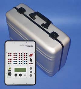
SA10 SWITCH TESTER
The SA10 equipment is designed to be used together with a personal computer even in those cases where fundamental tests can be performed without human presence (standalone).
There are many advantages to using a personal computer: versatility, customized solutions, simplicity...
Just take the computer to your office, select the tests, analyze test results, print test reports, etc.
Together with the BTS11 software, a personal computer and a printer, this is the most reliable, capable, accurate and easy-to-use field switch test equipment available on the market. Experienced engineers and service personnel have used the SA10 for many years in some of the world's harshest environments and have given it a good positioning in the world market.
General features
- Housed in a small metal carrying case.
- Fully compatible with our online factory test equipment
- No switches on the panel, just two buttons that are pressed to open and close.
- Supports digital and analog transducers
- The only field test equipment with a built-in micro-ohm measurement function. 200A!
- Possibility to use the "first shot" analysis method
- It weighs only 11.6 kg/26 lb.
- Automatic current/voltage measurement of coil and motor.
Synchro-switches
After switching e.g. capacitor banks, shunt rectors and power transformers it is common to use a synchro-switch relay for the circuit breaker.
The SA10 allows complete analysis of the wave point manoeuvring technology.
Communication
The equipment comes with a standard RS232 communication interface. However, in order to comply with safety regulations, a bluetooth communication kit is available that allows the user to move away with their laptop up to 100m (328ft) from the test object.
Static and dynamic resistance
This unique field test equipment with a built-in micro-ohmmeter is a complete and versatile unit. It generates 200 ADC and the value is automatically recorded
in the system along with their other measures. In order to visualize the exact behavior of the switch's pole during an operation, the dynamic resistance measurement function offers great diagnostic possibilities.
Motion measurements
The SA10 supports both analogue and digital transducers. A wide range of transducer couplings can be supplied. Elcon International is the official worldwide supplier of transducer couplings for ABB circuit-breakers.
Number of inputs on digital transducers: 3.
Number of inputs on analogue transducers: 3.
Analog inputs
Everything on all SA10's has 11 analog inputs, however as our intention is to provide you with a user-friendly and circuit-breaker oriented test set they have been pre-set to handle specific relevant functions such as coil and motor voltages, currents, analog signal transducers, etc. Of course it is possible to adjust most of the inputs to handle other types of related input signals, such as pressure or temperature sensors or any other type of analog signal that is relevant.
First shot or online analysis
In order to fully evaluate the condition of the breaker mechanism, the SA10 provides inputs to test the breaker during an on-line operation. This way, the first trip of a breaker that has been stationary for a long time can be captured and through that display determine the performance of the breaker in an actual fault situation. Both trip and close operations are possible online.
Contact time
The contact input modules of the SA10 supply 120 VDC on open contacts and 100 mA on closed contacts. The evaluation logic also distinguishes between a possible pre-insertion and the main contact in the same operation. It is also possible to measure the value of the pre-insertion resistor with a reference shunt. The time for both the pre-insertion and the main contact is guaranteed in any substation yard and at any voltage level.
Number of main contact time channels: 12(x2)
Number of auxiliary contact channels: 6.
(The auxiliary inputs can also be used as main contact inputs in low induction environments).
Coils and Motor
Automatic measurement of motor and switch coil current/voltage. Together with an adjustable power unit it is very easy to perform minimum function voltage test on the coils.
The SA10 uses an analog channel to measure coil voltage and current, and a channel to measure motor voltage and current.
For the coil 35A AC/DC for continuous measurement is possible, and for the motor 50A AC/DC. However, if required, higher currents will be passed through for shorter periods.
Ordering Information
SA10 Kit 1 Advanced DS002
This SA10 kit contains everything you need to perform standard tests on a circuit breaker, including a signal with a digital transducer.
Accessories circuit-breaker analyzer Amperis SA10
S001 - SA10 unit and software, kit with connection accessories, power cable, communication cable, soft-cable bag
S108-B Rotary digital transducer RSI503 2500ppr.
S205 Cable for digital transducer
S208-A (x3) Contact time cables.
S203 Cable for motor voltage and current measurement.
S204 (x2) Cable for voltage and current measurement of the coil.
S207 Static/Dynamic Resistance Cables
S113 Carrying case.
S210 Grounding cable.
All kits come complete with BTS11 system software with free upgrades, manuals, power cable, grounding cable, communication cable, connection accessories, soft cable bag and free stand.
INCLUDE TABLE FROM OLD WEBSITE (ATTACHED IMAGE)
BTS11 System Software
BTS11 Test Program
For complete testing of the breaker, the BTS11 analysis software is used. The software is free of charge and is delivered together with the SA10. This software is used for Elcon field test equipment as well as for factory test equipment. The data between the two different systems can be easily imported/exported. All updates are free of charge and can be downloaded from our website.
To test switches in general, it is to operate the switch and check the contact time. However, in factory testing and field service other tests are needed. For field testing these other tests can also be very useful for diagnostic purposes.
Common operating tests can be done with resulting time diagrams for up to three phases, each with a travel curve, up to twelve contact curves and a common coil current curve. All common tests are performed and evaluated according to established industry standards. A new test, mainly for field diagnostics, is to take dynamic resistance test curves from a main contact in operation. A spring tension test, with current time diagram is also included.
One of the main intentions with our software is to allow any level of user to be able to test the switch. This is done by creating a database of your breaker types and allowing the user to choose their breaker from that database and having everything (test plan, test reports, parameters, etc.) automatically adjusted to meet that test.
Let's keep it simple.
Some features of the BTS11:
- Simple operation control function for all possible tests.
- Quick test. No adjustments needed.
- Possibility of automatic test sequences.
- Test guides for new tests and test objects.
- Curve analysis window with many possibilities and tools
- Data analysis function with limit monitoring and comparison possibilities with a pre-test. (Reference characteristics IEC62271-100).
- Possibility to customize any operation in order to adapt the software to any type of switch.
- Statistical analysis.
- SQL database or access database with several users and user levels
- Import and export of test data.
- Automatic unit conversion. (ex: kg to lb or mm to inches).
- Test against function values (measurement limits)
- Easy to establish your own test profile.
- Attach photographs or reference documents to assist the user.
EC - Elcon Competence Center
ECC offers different levels of software and hardware training.
We believe in real hands-on experience, much better than any manual. Students take the actual test under the supervision of the instructor.
Choose between different levels, basic or advanced. ECC offers training at our facility in Sweden. The customer can also choose ECC's FLEXION, which means that we send you our instructor; also the program can be more adapted to your special testing needs.
Please contact us for more information and a quote.
Example of operations
Example of operations graph Amperis SA10 circuit-breaker analyzer
- Close
- Opening
- O-C, C-O, O-C-O
- Any combination of O and C
- Min coil voltage function
- Spring load (motor current)
- Sliding Coupling
- Damping curve
- Static resistance
- Dynamic resistance
- Disconnector test
- Pre-insertion resistors
- Operations tailored to the user (e.g. for long sequences for medium voltage switchgear)
Other possibilities and test features
Graph of other test features of the Amperis SA10 circuit breaker analyzer
- Up to 3 mechanisms with up to 12 contact elements per phase
- Establish your own test sequence
- Define the conditions for releasing the spring from the mechanism.
- Contact, coil, travel or analogous release.
- Choose the sampling rate. Up to 50 kHz.
- Up to three analog and/or digital transducers used simultaneously.
- Curve completely tailored to the user. Color, visibility, full or regular, scale etc.
- Easy to use functions/guidelines for calibration
- Speed and acceleration curves.
- Define any number of speed, distance or time measurements.
- First shot analysis
- Synchro-switch relay test.
SA10 Hardware Specification
- Number of main contact time channels: 12 (x2)
- Closed contact current with internal source: 100 mA
- Pre-insertion resistance range (standard version): 50 - 5000 ohm
- Current disturbance immunity (standard version): ±10 mApk
- Number of auxiliary contact time channels: 6
- Closed auxiliary contact current with internal source: 1 mA
- Contact voltage with external source: +15 - +400 VDC
- Reaction time, any timing channel: < 20 microsek
- Input connectors, any weather channel: Touch-protected connectors
- Protection level, any time channel: 3
- Coil source inputs in operation (Uc, COM): 1
- DC measuring range of the source voltage: 0 - 300 V ±1% or ±1 V
- AC measuring range of the source voltage: 0 - 300 V ±2% or ±2 V
- Number of coil outputs in operation (OPEN, CLOSED): 2
- DC measuring range of the coil current: 0 - 30 A ±1% or ±0.1 A
- AC coil current measurement range: 0 - 30 A ±2% or ±0.2 A
- Reaction time when releasing coil: < 20 microsek
- Internal current limit: 35 A
- Number of contact resistance measurement inputs: 1
- Resistance measurement range: 0-1000 microOhm
- Resistance measurement accuracy: ± 2 microOhm
- Resistance measurement current: 200 A
- Current generator source capacity: ≥ 4 V
- Resistance measurement input connector: Touch-protected connectors
- Current generator output connector: High current pole terminals
- Protection level of the resistance measurement inputs 1): 2
- Protection level of the current generator outputs: 1
- Protection level 1 (external connections and box)
- ESD resistance: IEC 1000-4-2 L4
- Radiated Electromagnetic Field Res (27-1000 MHz): IEC 1000-4-3 L3
- Explosion resistance (Burst): IEC 1000-4-4
- Pulse resistance: IEC 1000-4-5
- Protection level 2 (total insulation)
- Protection according to: Level 1
- Allowed between contact point(s) and ground: ≤±400 VDC, 285 VAC
- Protection level 3 (total isolation, total protection)
- Protection according to: Level 2
- Permitted between any level 3 contact point: ≤ ±400 VDC, 285 VAC
- Number of transducer inputs: 6
- Type of digital input receiver: RS422
- Analog input measuring range: 0 - 5 V
- Analog input impedance: 200 kohm 30pF
- Minimum resistance of analogue transducer: 100 ohm
- Power supply, both: 5 V, 100 mA
- Input connectors, transducer channels: LEMO Series 2K, 8 p
- Protection level any transducer input: 2
- Number of auxiliary inputs (Uk, Ul, Um, COM): 3
- DC measuring range of the input voltage: 0 - 300 V ±1% or ±1 V
- AC measurement range of the input voltage: 0 - 300 V ±2% or ±2 V
- Input impedance: 1 Mohm 30pF
- Number of outputs (Supplied by Um's ENGINE): 1
- DC motor current measurement range: 0 - 50 A ±1% or ±0.1 A
- AC measurement range of motor current: 0 - 50 A ±2% or ±0.2 A
- Input contacts, coil and auxiliary inputs/outputs: Touch-protected connectors
- Protection and auxiliary level coil inputs/outputs: 3
- Serial communication interface type: RS232
- Serial communication speed: 115 kbps
- Serial communication connector type: 9-pin D-sub female
- Serial communication protection level: 2
- Power supply AC input voltage: 85 - 265 V, 50 - 60 Hz
- DC input voltage of the power supply unit: 100 - 375 V
- Power requirement: < 50 VA
- Main fuse: 2 At
- Internal battery (lead-acid): 12 V, 6 Ah
- Input connector type: IEC320
- Protection level of the power input pins: 3
- Internal sampling rate (adjustable): 10Hz - 50 kHz
- Example 1 of maximum sampling time: at 100Hz 211Sek
- Example 2 sampling times: at 50kHz 400ms
- Ambient operating temperature range: -20° - +50° C
- Storage ambient temperature range: -40° - +70° C
- Relative ambient humidity (non-condensing): 0% - 97%.
- Dimensions: 458x331x153 mm (18"x13"x6")
- Weight: 11.7 kg
- SA10 Hardware Specification
- Acknowledgements: SA10 complies with the requirements for conformity in (Electromagnetic Compatibility). EMC Directive 89/336/EEG,
- 92/31/EEG and the Low Voltage Directive 73/23/EEG and 93/68/EEG including the addenda to the CE Marking Directive 93/68/EEG, and is CE marked. The SA10 is today the only field test equipment, on the market, which can perform circuit-breaker analysis accepted by ABB Switchgear.
- Warranty: 2 years
Download the catalogue of Switch Analyser SA10.
If you want to acquire Switch testing equipment with quality, you can also consult prices of Switch testing equipment.
If you have any doubts or need advice from our engineers, don't hesitate to contact us and we will be pleased to help you. You can also call us at (+34) 982 20 99 20.