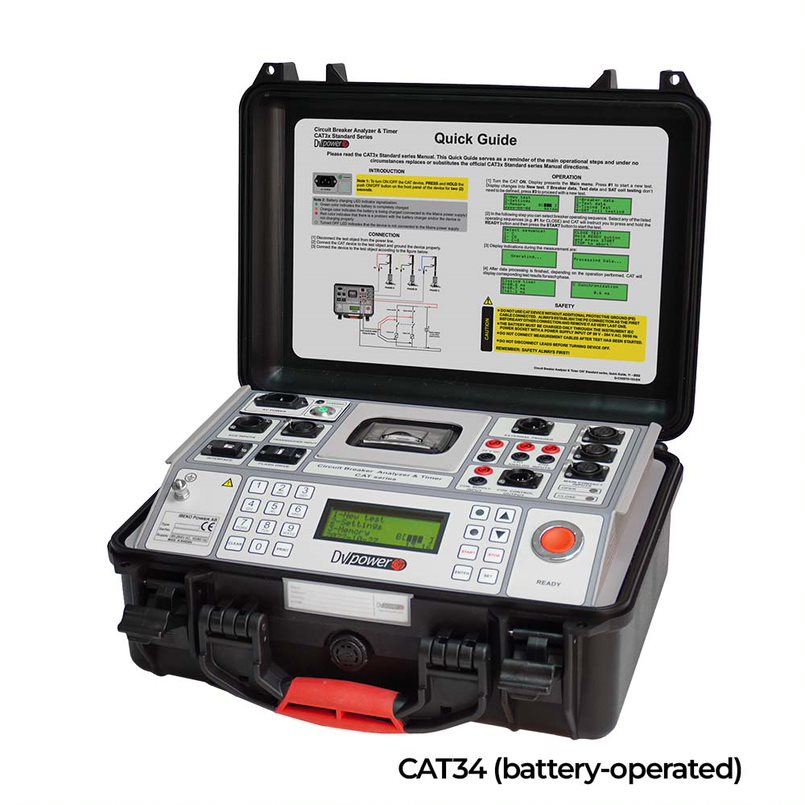
CAT SERIES ESTÁNDAR
- Simple and easy to operate
- Robust design for field use
- Accurate measurement in high voltage environment
- Timing and motion measurement
- Voltage and current measurement
- Detailed analysis of test results using DV-Win software
Description
The CAT Standard series circuit breaker analyzers & timers are stand-alone or a PC-controlled digital instruments for circuit breakers condition assessments. The timing channels record closing and opening of the arcing, resistor, and auxiliary contacts. CAT Standard series records graphs of both, trip and close coil currents and displacements of the HV and MV circuit breaker moving parts. The main contact channels can also measure the resistance value of the pre-insertion resistors (if present in the circuit breaker). Test results can be downloaded to a USB memory stick or saved to internal memory. The CAT Standard series internal memory can store up to 500 test results (numerical and graphical data). Test results can also be printed on the 80 mm (3.15 inch) thermal printer (optional accessory) in tabular and graphical form. CAT Standard series provides an easy selection of different operational modes:
- Trip (O)
- Close (C)
- Reclose (O-0,3s-C)
- Tripfree (CO)
- O-0,3s-CO
- Trip-Close (O-C)
- Close-Trip (C-O)
- Trip-Close-Trip (O-C-O)
Multiple operations, such as Trip-Close and TripClose-Trip, can be initiated by using a predefined delay time or by sensing a breaker’s contact position. The circuit breaker operation can be initiated in different ways (for instance from a control room, by a local switch or externally by a testing device) depending on the testing condition. Several time measurement triggers are available to record measurements in various testing conditions:
- external trigger
- analog channels
- auxiliary channels
- coil control channel The auxiliary inputs are used to monitor dry and wet auxiliary contacts.
The external trigger input can be used as the additional auxiliary input. The two coil control analog channels can measure and record the coil currents simultaneously (TRIP and CLOSE), up to 35 A AC/DC. The two additional analog channels have four selectable voltage ranges available (±0,5 V, ±2,5 V, ±60 V and ±300 V AC/DC). They can be used to monitor:
- Circuit-breaker substation battery voltage,
- Motor voltage and current,
- Other types of analog signals that may be relevant.
The transducer channel is intended for measuring the displacement of the circuit breaker moving parts, contact wipe, over-travel, rebound, damping time, and average velocity. Either an analog or a digital transducer can be connected to this universal channel.
Application The list of the instrument applications includes:
- Simultaneous timing measurement of up to 6 main contacts (2 breaks per phase) including preinsertion resistors (if present in the circuit breaker) and 3 auxiliary contacts,
- Resistance measurement of the pre-insertion resistors (if present in the circuit breaker),
- Evaluation of synchronization (simultaneity) between the circuit breaker poles.
- A measurement of the coil currents, simultaneously for 2 coils,
- Evaluating the state of the substation’s batteries by graphically showing the voltage value,
- A measurement of displacement, contact wipe, over-travel, rebound, damping time and average velocity of the breaker’s moving parts.
Timing Measurement
Timing measurement of mechanical operations is one of the most important tests to determine the real condition of the circuit breaker. Timing measurement tests fulfill all the requirements defined by IEC 62271-100 and IEEE C37.09. In three-phase systems, not only the contacts in a single-pole have to operate simultaneously, but all poles must also operate at the same time. All contacts must be synchronized, within a certain tolerance limit. Synchronization between the circuit breaker poles during opening shall not exceed 1/6 of the rated frequency cycle (3,33 ms at 50 Hz; 2,78 ms at 60 Hz) and during closing shall not exceed 1/4 of the rated frequency cycle, as well (5,0 ms at 50 Hz; 4,17 ms at 60 Hz). Simultaneous measurements within a single phase are important in situations where a number of contacts are connected in series. The maximum difference between the instants of contact separation within series connected interrupter units shall not exceed 1/8 of a cycle of rated frequency (2,50 ms at 50 Hz; 2,08 ms at 60 Hz). Maximum difference between the instants of contacts touching within series connected interrupter units shall not exceed a 1/6 of a cycle of rated frequency (3,33 ms at 50 Hz; 2,78 ms at 60 Hz). Auxiliary contacts are mechanically driven by the operating mechanism and are used for control and indication of the main contacts state. There are no general requirements, related to timing measurement of auxiliary contacts, described in IEC® and IEEE® standards. Anyway, in order to assess the condition of high-voltage circuit breakers, it is important to check their operation. Type "a" contact follows circuit breaker main contact position and must close/open ahead of the closing/opening of the main contact. Type "a" contact is connected in series with the trip coil and interrupts the trip coil circuit when the circuit breaker opens. The "b" contact must open/close when the operating mechanism has released its stored energy in order to close/open the breaker. Type "b" contact is connected in series with the closing coil, interrupting the closing coil circuit when the circuit breaker closes.
Motion measurement Motion measurement of the high voltage circuit breakers’ contact system is of crucial importance for assessing a condition of the test object. The three motion transducer channels can acquire data from 3 linear or rotary motion transducers. Each channel can be configured for either an analog or a digital transducer. Due to universal transducer channels design, a user is able to connect a variety of motion transducers available on the market. Performance values such as stroke, over-travel, rebound, contact wipe are obtained as a result of the measurement. These values can be compared to the manufacturer’s reference data and data acquired from previous measurements. This provides indications about potential wear of the breaker. Average velocity is calculated between the two points on the motion curve. The upper point is defined as a distance in length or time elapsed from the breaker’s closed position, or contactseparation point. The lower point is determined based on the upper point. It can either be a distance below the upper point or a time before the upper point.
User is usually allowed to mount transducers on accessible parts of the circuit breaker’s mechanical linkage. Beside this, instrument often records rotary motion, even it is known the main contacts motion is linear. As a result, motion results obtained do not represent real movement of the main contacts, but just linear or nonlinear interpretation of the main contacts moving parts displacement.
A-Win software provides transfer function feature which allows user to define linear or nonlinear parameters in order to obtain actual displacement values of the main contact moving parts.
Coil current measurement
The IEC 62271-100 standard states that it is desirable to record the coil currents waveform, since it provides information about coils’ condition (e.g. increased friction of the plungers, burned insulation, short-circuited part of the winding), the latch for release of the operating mechanism (e.g. increased friction) and the operating mechanism (e.g. if there is reduced operating mechanism speed that can be seen based on the opening time of auxiliary contacts). When the opening or closing command is initiated, the coil is energized (point 1) and the current rises causing a magnetic field to apply a force on the iron plunger. When the force on the plunger exceeds the retaining force the plunger begins to move (point 2). The motion of the iron plunger induces an EMF in the coil, effectively reducing the current. The combined mass of the plunger and the latch continue to move at a reduced velocity causing a further reduction in the coil current (points 2-3) until it hits a buffer bringing it to a rest (point 3). If the current values at points 2 and 3 are higher than specified and the time at point 3 is longer than specified, it may indicate a friction of the plunger and latch. With the plunger at rest, the current increases to the saturation level (DC current which is proportional to the coil resistance, point 4). If the current value from point 4 to point 5 deviates from specific it may indicate a burned insulation or short-circuited part of the winding of coil. Meanwhile, the latch unlocks operating mechanism, releasing the stored energy to open the main breaker contacts. Typically, after a short delay the auxiliary contacts open, disconnecting the opening coil from the control voltage (point 5). As the coil is de-energized the current drops quickly to zero in accordance with the coil inductance (point 6). Longer time than specified at points 5 and 6 may indicate auxiliary contact malfunction or insufficient driving energy of the operating mechanism.
If you want to acquire Equipos de prueba de interruptores with quality, you can also consult prices of Equipos de prueba de interruptores.
If you have any doubts or need advice from our engineers, don't hesitate to contact us and we will be pleased to help you. You can also call us at (+34) 982 20 99 20.