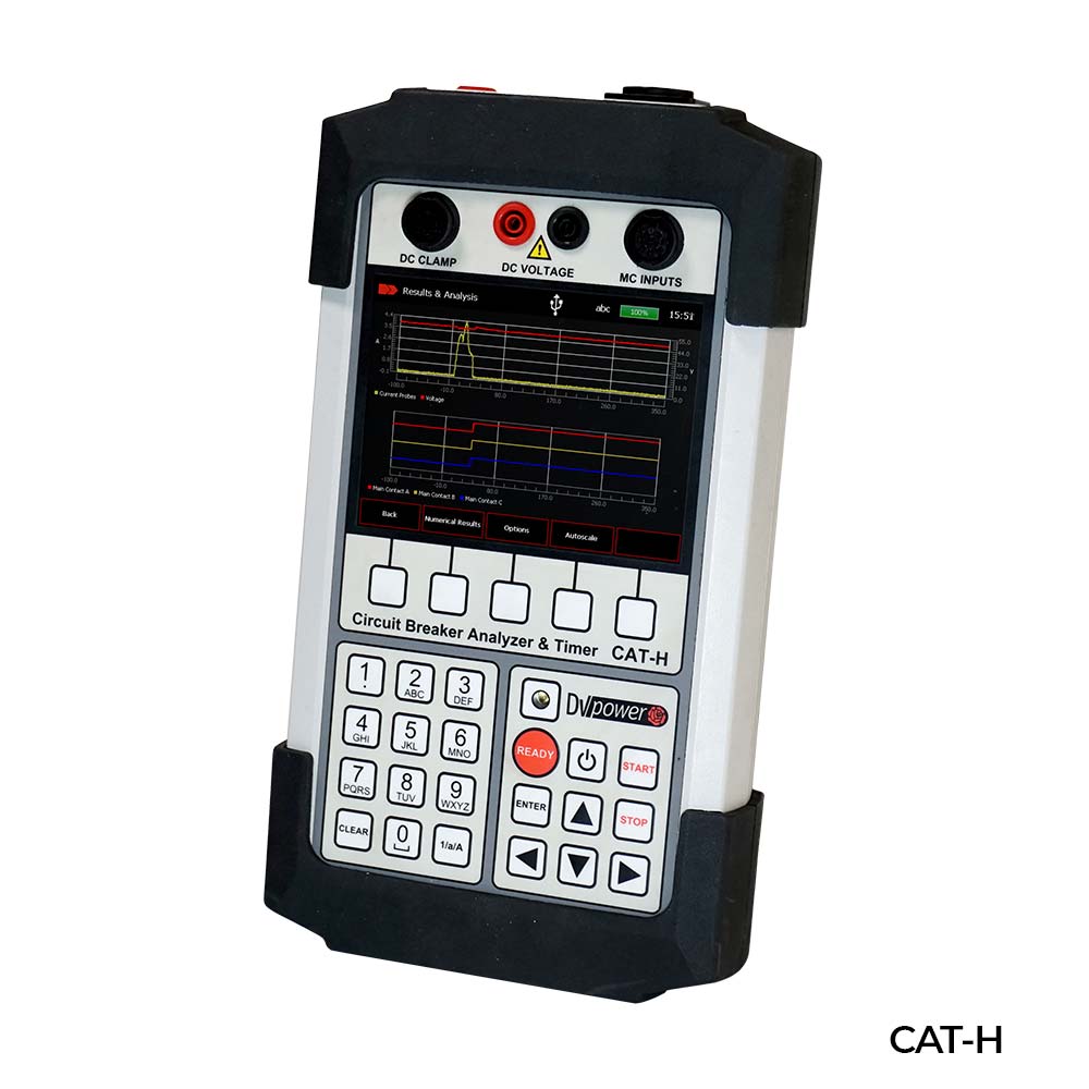
CAT-H SERIES SWITCH TESTER
CAT-H offers easy selection of different operating modes:
Open (O)
Close (C)
Free trip (CO)
Closing (O-C)
Close-Open (C-O)
Open-Close-Open (O-C-O)
Multiple operations, such as Open-Close and Open-Close-Close, can be initiated using a predefined delay time or by detecting the contact position of a switch.
The operation of the breaker can be initiated in different ways (e.g. from a control room, by a local breaker or externally by a test device) depending on the test conditions. Various time measurement triggers are available to record a measurement under a different test condition:
Coil control channel
Continuous current clamping channel
DC voltage channel
CAT-H is a powerful diagnostic tool for recording and analysis:
Operation of the main arcing contacts
Operation of the trip/closure coils
Operation of the auxiliary contacts
Supply voltage
Control circuit wiring integrity
CAT-H displays both numerical and graphical results (it can overlay up to 4 records in graphical form). This allows a quick on-site analysis of possible defects by comparing the test results obtained.
Compact and ergonomic design - only 1.6 kg (3.5 lbs)
Simple and easy to operate
Battery operation up to 8 hours
Measurement of time delay and coil current
Coil control (built-in) for OPEN and CLOSED coil
Graphical results for quick interpretation
145 mm (5.7 in) color touch screen
On-site analysis of test results. (superimpose up to 4 records in graphic form)
Application
The list of applications of the instrument includes:
Timing of up to 3 main contacts (1 break per phase) including pre-insertion resistors (if present in the breaker) and auxiliary contact
Measurement of the resistance of the pre-insertion resistors (if present in the breaker). Measurement of the bounce time of the main contacts.
Evaluation of the synchronization between the breaker's poles.
Measurement and graphical representation of the coil currents.
Coil monitoring (built-in) for actuating the opening and closing coil of the circuit breaker.
Evaluating the substation battery status (or other types of analog signals that may be relevant) by numerically and graphically displaying the voltage value.
Time measurement
The measurement of the time of the mechanical operations is one of the most important tests to determine the actual state of the circuit breaker. The timing measurement tests meet all the requirements stipulated in IEC 62271-100 and ANSI C37.09.
In three-phase systems, not only the single-pole contacts have to operate simultaneously, but all the poles must also operate at the same time. All contacts must be synchronized, within a certain tolerance limit.
The synchronisation between the poles of the circuit breaker during opening should not exceed 1/6 of the nominal frequency cycle (3.33 ms at 50 Hz; 2.78 ms at 60 Hz) and during closing should not exceed 1/4 of the nominal frequency cycle (5.0 ms at 50 Hz; 4.17 ms at 60 Hz).
Simultaneous measurements within a single phase are important in situations where several contacts are connected in series.
The CAT-H can be used to measure the operating times of the main arcing contacts when the breaker is isolated from the mains or is being tested elsewhere, such as at the manufacturer's premises or in a maintenance workshop. When test connections are made, the switch must be disconnected or separated from its circuit on both sides of the switch according to national safety regulations. The switch must be properly grounded to a protective earth.
The auxiliary contacts are mechanically operated by the control and are used to monitor and indicate the status of the main contacts. There are no general requirements related to the measurement of the timing of the auxiliary contacts, described in the IEC® and ANSI® standards. However, in order to evaluate the condition of high-voltage switches, it is important to verify their operation.
IEC 62271-100 states that it is desirable to record the waveform of the coil currents, as this provides information on the condition of the coils (e.g. increased friction of the plungers, burnt insulation, short circuit in part of the winding), the release lock of the drive mechanism (e.g. increased friction) and the drive mechanism (e.g. if there is a reduction in the speed of the drive mechanism which can be observed as a function of the opening time of the auxiliary contacts).
When the open/close command is initiated, the coil is energized (point 1) and the current increases by causing a magnetic field to apply a force on the iron plunger. When the force on the plunger exceeds the holding force, the plunger begins to move (point 2). The movement of the iron plunger induces an EMF in the coil, effectively reducing the current.
The combined mass of the plunger and latch continues to move at a reduced speed, causing a further reduction in the coil current (points 2 to 3). until it reaches a stop and brings it to a standstill (point 3). If the current values at points 2 and 3 are higher than specified and the time at point 3 is longer than specified, this may indicate a friction of the plunger and latch. With the plunger at rest, the current increases to the saturation level (direct current proportional to the coil resistance, point 4). If the current value from point 4 to point 5 deviates from the specified, it may indicate a burnt insulation or a short circuit in part of the coil winding. Meanwhile, the latch releases the operating mechanism, releasing the stored energy to open the main switch contacts. Normally, after a short delay, the auxiliary contacts are opened, disconnecting the opening coil from the control voltage (point 5). As the coil is de-energized, the current drops rapidly to zero according to the inductance of the coil (point 6). A time period longer than that specified in points 5 and 6 may indicate a malfunction of the auxiliary contact or insufficient actuating energy of the control system.
DV-Win software
The DV-Win software provides the acquisition and analysis of test results. The graphical presentation of a variety of time measurements and test results uses cursors and powerful zoom functions for detailed analysis. The colors, grids, scales and positioning of the test data are user controlled.
A-Win supports automatic unit conversion (e.g. cycles to seconds or mm to inches). Test records can be exported in .cath file format for further analysis.
If you want to acquire Equipos de prueba de interruptores with quality, you can also consult prices of Equipos de prueba de interruptores.
If you have any doubts or need advice from our engineers, don't hesitate to contact us and we will be pleased to help you. You can also call us at (+34) 982 20 99 20.