Summary:
- Transformer Winding Resistance Measurements
- Winding Resistance Measurement
- Winding Resistance Measurement Case History
Transformer Winding Resistance Measurements
Purpose of the Measurements
Measuring the winding resistance of transformers is of fundamental importance in order to:
- Calculate the I²R component of conductor losses.
- Calculate the winding temperature at the end of a temperature test cycle.
- As a basis for assessing possible damage in the field.
Transformers are subject to vibration. Problems or failures occur due to poor design, assembly, handling, an unsafe environment, overloading or poor maintenance. Winding resistance measurement confirms that the connections are correct, and the resistance reading indicates that there is no serious mismatch. Many transformers have a built-in regulating tap. These taps make it possible to increase or reduce the ratio in fractions of a percent. Every ratio change involves a mechanical movement of a contact from one position to another. These tap changes will also be checked during Winding Resistance Measurements.
Regardless of the star or delta configuration, the measurements are made phase to phase and comparisons are made to determine whether the readings are comparable. Bear in mind that the purpose of the test is to assess gross differences between the windings and open circuits in the connections. The tests are not performed to duplicate the reading of the manufactured device, which was tested at the factory under controlled conditions and possibly at other temperatures.
Characteristics of a Transformer
A transformer is regarded as a passive device capable of storing and delivering finite amounts of energy. Practically all transformers use magnetic material to shape the magnetic fields that act as the medium for transferring energy. The relationship between the magnitude of the magnetic fields and the electrical circuits with which they interact plays an important role in describing the operation of the device. The magnetic material determines the size of the equipment and its capacity, and introduces limits due to saturation and loss of performance.
Fundamentally, a transformer consists of one or more windings linked by a mutual magnetic field. These windings are simply coils of wire, inductors. The characteristics of the transformer can now be analysed using a few simple formulas.
The voltage across an inductor is proportional to the time rate of change of the current flowing through it.
v= L di/dt
It must also be borne in mind that an abrupt change in the inductor current requires an abrupt change in the energy stored in the inductor, and this sudden change of energy requires infinite power at that instant; infinite power is not part of the real world. The inductor current must be prevented from jumping instantaneously from one value to another. If an attempt is made to open the circuit of a physical inductor through which a finite current is flowing, an arc will appear at the switch. This is useful in the ignition system of a car, but hardly an event to witness during winding tests on a transformer.
The energy stored in an inductor carrying current can be represented by the formula:
w(t) = ½ I²L
Where, w(t) = Energy as a function of time
I = Current in amperes
L = Inductance in henries
Ahead of the desired current flow (for testing purposes), this energy requirement has to be satisfied and implies that some time requirement will also be necessary before the measurement can be taken. This time requirement applies only to the charging time. Additional time has to be allowed for the current to stabilise before taking the measurement.
The final time required to take a reading is limited by an inherent time lag between the application of a direct current and the time it takes for the core magnetisation to stabilise. Depending on the size and construction of the transformer, the test duration can be very short for small transformers or very long for larger, highly inductive transformers.
Test Equipment
Before modern digital and electronic equipment, the Kelvin double bridge was used. Batteries, switches, galvanometers, ammeters and slide-wire adjustments were used to obtain resistance measurements. Current regulators were built and inserted between the battery and the bridge. The 12 volt DC input voltage to the regulator, coming from an automotive storage battery, provided a variable output current in steps matched to the maximum current rating of the bridge within the ranges most commonly used on transformers.
The current regulator increased the speed and the accuracy of the bridge readings. The availability of approximately 11 volts was used to speed up the initial current build-up and dropped to about 5 volts just before the selected current was reached and regulation began. Once regulation began, the current was essentially constant despite the inductance of the windings and the fluctuation of the battery voltage or cable resistance.
Test duration has been greatly reduced by using modern microprocessor-based test equipment Direct readings can be obtained from digital meters with automatic indications that alert the operator when a valid measurement is available. On some testers there are two meters, allowing two simultaneous resistance measurements.
CAUTION
Because of the enormous amount of energy that can be stored in a magnetic field, precautions must be taken before disconnecting the test leads from the transformer under test. Never disconnect the leads during the test process and always allow enough time for the transformer to discharge completely before starting the tests. Large transformers may require several minutes to discharge.
Most new winding resistance meters today have indicators that tell you when the leads can be safely removed.
Principles of Operation
The basic idea is to inject a DC current into the winding to be measured, and then read the voltage drop across that winding.
Electrical test instruments apply the DC current through the winding and an internal standard current shunt. After measurement, the DC voltage drops are ratioed and the display is read as resistance on the front panel meter. This method allows the cable resistance to be disregarded, since the reading is independent of the current. In addition, no multiplication factors are needed when changing current ranges.
The DC current source has to be extremely stable. Referring to the DC voltage formula for a transformer shown below:
v = I * R + (L di/dt)
Where, vdc = Voltage of a transformer winding
I = DC current through the transformer winding
R = resistance of the transformer winding
L = inductance of the transformer winding
di/dt = rate of change of the current (ripple current)
We assume that the tester has a very stable source (that is, ripple-free), so di/dt is zero and the term L di/dt becomes zero.
Tap Changers
Tap changers are divided into two types: on-load and off-load. The on-load tap changer allows the ratio to be changed while the transformer is in operation. This means that the ratio of a transformer can be changed while current is flowing through it. The most common example of this type of on-load tap changer is the voltage regulator.
On-Load Tap Changer
The QRM-10P resistance meter is ideal for checking on-load tap changers, since the instrument can be left switched on while changing from one tap to another. This allows the operator to take measurements very quickly without discharging, and then charge the transformer again for each tap. The winding resistance tester rebalances after each tap change. If the tap is faulty (open) or if there is even a fraction of a second with the circuit open, the winding resistance tester will automatically start its discharge cycle. This gives the operator a clear indication, by means of a display light, of a possible fault inside the tap changer. Under this open-circuit condition, the test equipment will not cause any damage to the transformer.
Off-Load Tap Changer
This style of tap changer requires the tap changer to be discharged between tap changes. To change the tap, the transformer has to be taken out of service or at least disconnected from the load. This type of tap changer can generally operate less quickly than the previous type, because of unintended tap changes while in service. The resistance tester will still work on this tap changer, but it must be discharged between tap changes.
Safety
Although some aspects of the inspection can be carried out without de-energising the transformer, winding resistance measurement is not one of them. To ensure maximum safety for the worker, the high-voltage and low-voltage cables must be disconnected from the transformer. Preferably, there should be a visible gap between the transformer terminals and the high- and low-voltage lines.
Conclusion
Transformers are very reliable devices and will last many years if they are maintained regularly. Transformer failures, when they occur, are generally serious in nature and may require costly repairs and long downtime. The best insurance against a transformer failure is to ensure that they are properly installed and properly maintained. Make sure that Winding Resistance Measurement is included when testing a transformer. Modern self-contained instruments make testing easy and accurate. Keep a good record of the resistance values found and compare them with previous readings to see whether there are any deviations.
Winding Resistance Measurements
ANSI/IEEE - C57.12.90 - 1987
Resistance measurements are essential for the following purposes:
- CALCULATION OF THE I²R COMPONENT OF CONDUCTOR LOSSES
- CALCULATION OF THE WINDING TEMPERATURE AT THE END OF A TEMPERATURE TEST.
- AS A BASIS FOR ASSESSING POSSIBLE DAMAGE IN THE FIELD.
- 4.1. Determination of Cold Temperature The cold temperature of the winding shall be determined as accurately as possible when measuring the cold resistance. The following precautions shall be observed:
- 4.1.1 General Cold resistance measurements shall not be made on a transformer when it is located in draughts or located in a room where the temperature fluctuates rapidly.
- 4.1.2 Windings of Transformers Immersed in Insulating Liquid The temperature of the windings shall be assumed to be the same as the temperature of the insulating liquid, provided that:
- (1) The windings have been immersed in the insulating liquid without any excitation and without any current in the windings for 3h to 8h (depending on the size of the transformer) prior to the cold resistance measurement.
- (2) The temperature of the insulating liquid has stabilised, and the difference between the top and bottom temperature is not greater than 5ºC.
- 4.1.3 Windings of Transformers Without Insulating Liquid The temperature of the windings shall be recorded as the average of several thermometers or thermocouples inserted between the turns, taking care to ensure that their measuring points are as close as possible to contact with the winding conductors. It must not be assumed that the windings are at the same temperature as the surrounding air.
- 4.2 Conversion of Resistance Measurements Cold winding resistance measurements are normally converted to the standard reference temperature equal to the rated average winding temperature rise plus 20ºC. In addition, it may be necessary to convert the resistance measurements to the temperature at which the impedance loss measurements were made. The conversions are performed with the following formula:
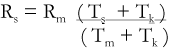

Where, Rs = Resistance at the desired temperature Ts
Rm = Measured resistance
Ts = Desired reference temperature
Tm = Temperature at which the resistance was measured
Tk = 234.5 (copper)
= 225 (aluminium)
Winding Resistance Measurement - Case History
Case History - Source - IEEE - C57.125 - 1991
C7 OVERHEATED JOINTS
This case history involves a 17.9/22.4 MVA - 34.5 - 13.8 kV AUTOTRANSFORMER with all-aluminium windings.
C7.1 UNSUITABLE FOR SERVICE - Abnormal DC resistance measurements were obtained between high-voltage terminals during routine maintenance testing. The results of the other tests were all normal.
This utility checks the DC resistance of all transformers with tap changers as a routine maintenance test to determine whether there is evidence of contact problems.
C7.2 DATA COLLECTION The following measurements were recorded:
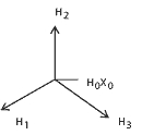  | Terminals | DC Resistance |
|---|---|---|
| H1 H2 | 0.142 | |
| H2 H3 | 0.153 | |
| H3 H1 | 0.153 | |
| H1 - H0X0 | 0.072 | |
| H2 - H0X0 | 0.072 | |
| H3 - H0X0 | 0.084 |