The most advanced technology for traction battery monitoring.
The Amperis integrated traction battery monitoring system performs the functions of Monitor, Manager and Logger and is designed to be installed on batteries of any type, voltage or capacity.
The system measures and records all the relevant battery operating parameters and communicates in real time via CANBUS, PWM or RS-232, allowing full integration with the vehicle control system, the charger and the rest of the accessories.
The latest technology in traction battery monitoring
- The most advanced control and protection system for batteries.
- Dust and vibration resistant (IP 54)
- Insulated connections
- CANBUS interface with HV insulation
- Simple system to install and configure.
- Rugged design, manufactured from oil- and acid-resistant materials.
The main measured parameters are:
- Total battery voltage
- Battery mid-point voltage
- Current (Integrated hall effect sensor)
- Temperature (Submersible probe)
- Electrolyte level (Submersible probe)
- Ah charged/ discharged per cycle
- Ah charged/ discharged in total
- State of charge (SOC)
- Number of cycles
**All the measured values are stored on a Micro-SD card.
Typical applications
- Forklift trucks and other industrial vehicles
- Airport ground support vehicles
- Stationary batteries
Interface
The monitor can be connected to external devices such as the vehicle ECU or the charger itself. All the parameters, events and alarms are available via CANBUS and RS-232.
The main alarms:
- Undervoltage / overvoltage
- Unbalanced battery voltage
- Low electrolyte level
- Overcurrent during operation
- Overcurrent during charging
- High/low temperature
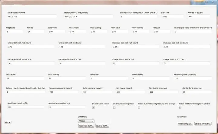
The user can define the normal operating ranges or limits for each parameter through simple PC software. The Amperis battery monitoring system allows communication with the charger, via the CANBUS or RS-232 interface, in order to control the charging process. (The charger must be ordered with the CANBUS option)
An auxiliary relay is optionally available (built into the design) that allows external alarms to be connected, providing an additional degree of protection for the battery.
| MODELS | Amperis battery monitoring system |
||
| POWER SUPPLY |
| TYPE | Battery monitoring system |
| INPUT VOLTAGE | Battery nominal voltage, 12 to 120V |
| FEATURES |
| SERIAL INTERFACE | RS-2332@ 115200 kb/s |
| CAN-BUS | According to J1339 protocol |
| MEMORY | 1 GB MicroSD, allows data to be stored throughout the whole service life of the battery. (With the appropriate configuration) |
| AUXILIARY RELAY | NC relay, opens in the event of alarms. |
| ALARMS |
| OVERVOLTAGE | 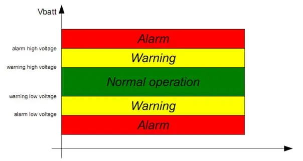 |
| UNDERVOLTAGE |
| ELECTROLYTE LEVEL | The system will generate an alarm (Warning/alarm) if the battery electrolyte level drops below a limit. |
| HIGH CURRENT ON CHARGE | The system monitors the current value during the charge and discharge cycles. If the current value exceeds the limit preset in the configuration file, an alarm will be generated. |
| HIGH CURRENT ON DISCHARGE |
| OVERTEMPERATURE | The system uses the same control algorithm for temperature as the one shown for voltage. In the event of overtemperature or too low a temperature, an alarm or warning will be generated. |
| TEMPERATURE TOO LOW |
| MECHANICAL DESIGN |
| DIMENSIONS | 128X55X52 (mm) |
| ENCLOSURE | Made from oil- and acid-resistant plastic material. |
| COOLING | Natural |
| DEGREE OF PROTECTION | IP 54 |
| AMBIENT TEMPERATURE | Operation: -10/+50 ºC
|
| UNDERVOLTAGE |
| ELECTROLYTE LEVEL | The system will generate an alarm (Warning/alarm) if the battery electrolyte level drops below a limit. |
| HIGH CURRENT ON CHARGE | The system monitors the current value during the charge and discharge cycles. If the current value exceeds the limit preset in the configuration file, an alarm will be generated. |
| HIGH CURRENT ON DISCHARGE |
| OVERTEMPERATURE | The system uses the same control algorithm for temperature as the one shown for voltage. In the event of overtemperature or too low a temperature, an alarm or warning will be generated. |
| TEMPERATURE TOO LOW |
| MECHANICAL DESIGN |
| DIMENSIONS | 128X55X52 (mm) |
| ENCLOSURE | Made from oil- and acid-resistant plastic material. |
| COOLING | Natural |
| DEGREE OF PROTECTION | IP 54 |
| AMBIENT TEMPERATURE | Operation: -10/+50 ºC
Storage: -20/+70 ºC |
| CONNECTIVITY |
| USER INTERFACE AND PC SOFTWARE | RS-232 port (real-time control)
Micro SD card (storage memory)
PC software, compatible with Microsoft Windows XP/Vista/7, made up of:
- Configurator: for configuring alarms, limits and other options.
- Real-time monitor: display the measurements in real time (BCAN)
- Data Analyzer: Analysis, graph display and off-line data download. |
| ** ** | EMC: IEC EN 61000-6-2, IEC EN 61000-6-4 |
| STANDARDS | Safety: IEC EN 50178, IEC EN 62040-1
CE marking |
Software package
The system suite is a complete tool that allows you to control, manage and configure your monitoring system:
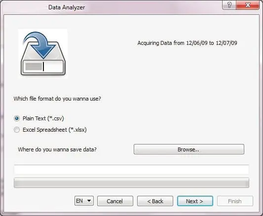
- Data analyzer: a simple Windows window will guide you through the whole analysis process:
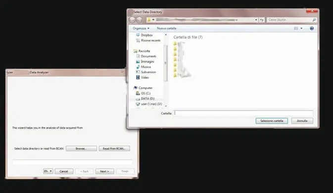
- Off-line analysis of the data taken from the SD card.
- Data acquisition through the serial port, directly from the monitor.
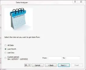
- a. Selection of the time window to be analysed
- b. Selection of the file format to be generated: CSV or XLSX (Excel)
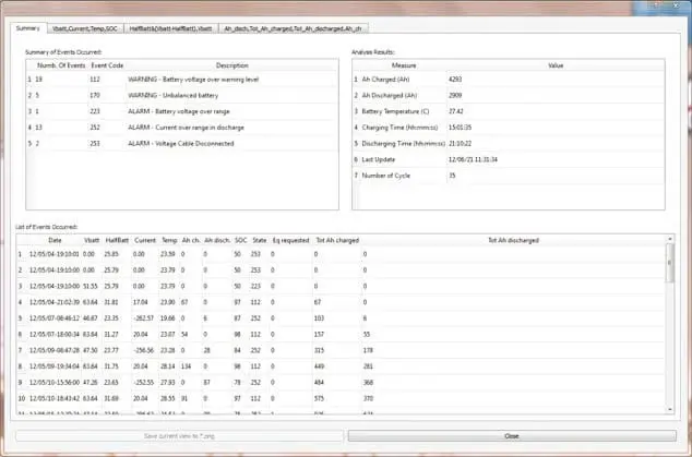
- c. An integrated system displays all the selected data together, for immediate understanding of how the system is operating.
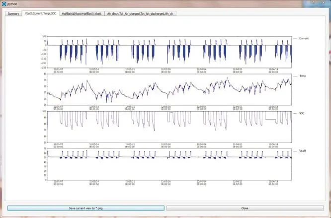
- d. Intuitive display of the logged data (voltages, current, temperature, SOC, Ah, partial and total)
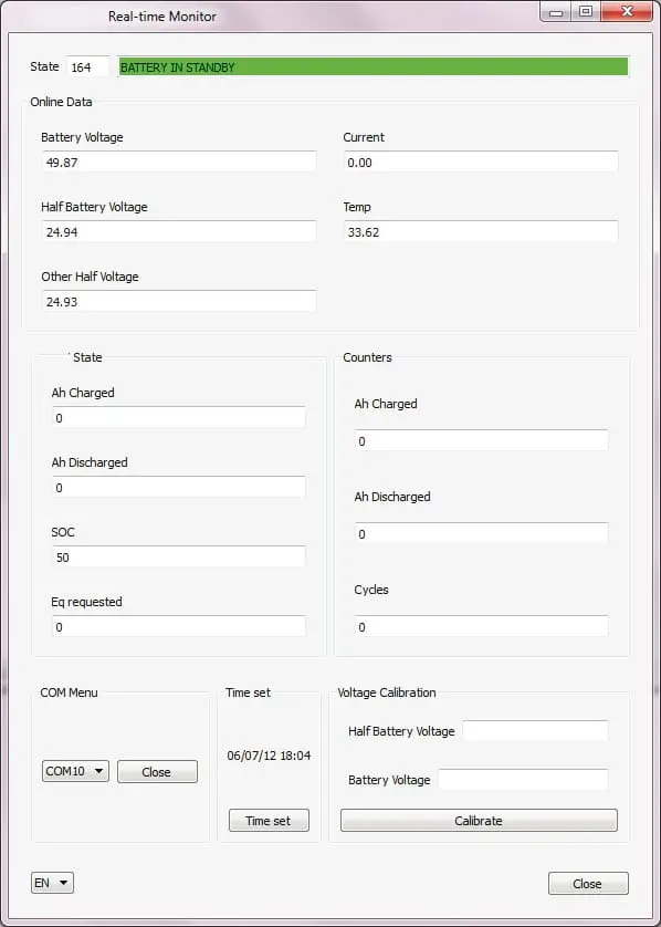
- Real time monitor: connect to your monitor and view all the measurements in real time. This is the fastest tool for checking the correct operation and configuration of your monitoring system.
- Monitor configurator: software tool for configuring the alarm limits and the storage options.