POB35AD
CIRCUIT BREAKER TESTING AND DIAGNOSTICS
Summary: The addition of the CPS150 programmable power supply —5 kVA in both alternating and direct current— alongside the existing POB35AD turns the SA10A analyser into a single platform: trip and closing coils and spring charging motors tested on the same bench, whatever their supply technology. Each power supply works at what it was designed for, and the historical bottleneck of DC-only arrangements disappears.
Amperis Products S.L. · Technical documentation · Diagram AMP-SA10-CNX-001, Rev. B
The technical verification of circuit breakers requires responding to the diversity of electrical configurations found in substations. For years, tests on trip and closing coils using the SA10A analyser relied on direct-current-only power supplies such as the POB35AD. The arrangement was well suited to conventional operations, but it presented severe energy limitations when driving spring charging motors supplied in alternating current, to the point of compromising the integrity of the supply itself through overload. With the integration of the CPS150 —5,000 VA switchable between AC and DC, up to 300 V AC and 424 V DC— that bottleneck is overcome.
The limit of the DC-only arrangement
The POB35AD remains an excellent instrument for what it was conceived to do: deliver stable, filtered voltage to the operating coils —from 10 to 300 V DC and from 10 to 250 V AC on independent opening and closing outputs— and supply the spring charging motor with up to 30 A in direct current when the substation battery is not available. Its ripple below 1 % in DC is what makes it possible to analyse coil current traces reliably, and its automatic minimum trip voltage test meets the requirements of IEC 62271-100 and ANSI C37.09.
The problem did not lie in the quality of the power supply, but in the nature of the test. An AC spring charging motor presents a starting profile —high inrush current, high crest factor, several seconds in duration— that an output designed for direct current cannot take without degrading. The technician was left with one of two options: give up testing the motor under real service conditions, or set up a second test bench with its own AC supply, duplicating cabling, connection time and workspace.
The CPS150 power supply: 5 kVA programmable in AC and DC
The CPS150 is a benchtop or 19″ rack programmable power supply with a colour touchscreen and power connectors on the rear panel. It is built on digital signal processing and programmable logic, and supports full control through SCPI commands.
| PARAMETER | VALUE |
|---|---|
| Type | Single-phase AC and DC programmable power supply |
| Power | 5,000 VA / 5,000 W |
| AC output voltage | 0–150 V (low range) / 0–300 V (high range) |
| DC output voltage | 0–212 V (low range) / 0–424 V (high range) |
| Output current | AC: 46 A (150 V) · 23 A (300 V) — DC: 32.6 A (212 V) · 16.3 A (424 V) |
| Resolution and accuracy | 0.1 V · ±(0.3 % of reading + 0.3 % of full scale) |
| Mains supply | 190–265 V AC, single-phase (L, N, G), 47–63 Hz |
| Communications | USB, RS-232 and RS-485 as standard (LAN / GPIB optional) |
| Protections | Overcurrent (OCP, fold-back), overvoltage (OVP) and overtemperature (OTP) |
Three capabilities make the difference against a conventional power supply. Support for crest factors of up to 5:1 or 6:1, which allows the inrush of real loads such as spring charging motors to be evaluated. Programmable voltage ramps (slew rate in V/ms), which limit the starting current in a controlled way instead of applying the full step. And fold-back current limiting, which is configured before energising and protects both the coil under test and the analyser inputs. Added to this are the integrated measuring instrument —up to fifteen simultaneous quantities— and the LIST, STEP and PULSE transient modes, which open the door to repetitive sequences and to the simulation of supply disturbances on the breaker control circuit.
The new AMP-SA10-CNX-001 connection diagram
The diagram developed by Amperis consolidates the simultaneous testing of coils and motor by taking advantage of the fact that the analyser has two independent supply input blocks, and by dividing the work between the two power supplies:
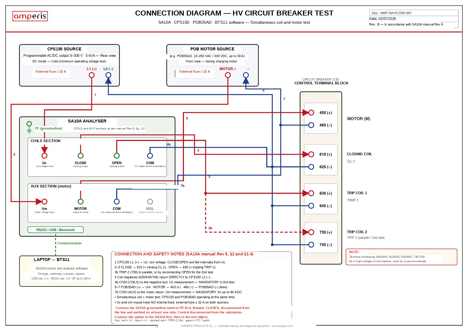
Doc. AMP-SA10-CNX-001, Rev. B — Circuit breaker testing (HV) with SA10A, CPS150, POB35AD and BTS11 software. In accordance with the SA10A manual Rev. 6. The terminal numbering (450/465, 610/625, 630/645, 730/745) corresponds to a high-voltage circuit breaker taken as a typical example.
Division of functions between the two power supplies
The CPS150 supplies the coil block: its L1 (+) output goes to the Uc terminal of the COILS section and its L2 (−) return collects the coil negatives. From Uc, the analyser itself internally feeds its CLOSE and OPEN outputs, wired to the CL-1 closing coil (terminal 610) and to the TRIP-1 trip coil (terminal 630). This is the configuration used to determine the minimum operating (pick-up) voltage. The POB35AD supplies the AUX section: its positive goes to the Um terminal, from which the analyser feeds its MOTOR output to terminal 450, with the return through 465 directly to the negative of the power supply. TRIP-2 (terminal 730) can be connected in parallel with TRIP-1 or reconnected to OPEN for a second independent test.
| ELEMENT | POWER SUPPLY | INPUT | OUTPUT | CIRCUIT BREAKER TERMINALS |
|---|---|---|---|---|
| Closing coil CL-1 | CPS150 | Uc / COM | CLOSE | 610 (+) / 625 (−) |
| Trip coil TRIP-1 | CPS150 | Uc / COM | OPEN | 630 (+) / 645 (−) |
| Trip coil TRIP-2 | CPS150 | Uc / COM | OPEN (parallel or 2nd test) | 730 (+) / 745 (−) |
| Spring charging motor | POB35AD | Um / COM | MOTOR | 450 (+) / 465 (−) |
The return to the COM buses of both sections is not optional in this arrangement: it is the connection that enables voltage monitoring, so without it the measurement of Uc and Um is lost. The coil negatives (625, 645, 745) must return directly to the negative bus of the CPS150.
Can the roles of the two power supplies be swapped?
This is the question that arises as soon as the diagram is in front of you. Electrically, yes: both power supplies cover the voltage and current ranges of the two circuits —the POB35AD delivers from 10 to 250 V AC and up to 300 V DC with 30 A, and the CPS150 reaches 300 V with up to 46 A in the low range— and the SA10A is agnostic in this respect, because its Uc and Um inputs accept up to 300 V and 32 A each regardless of which power supply is behind them. Technically, it is not advisable, for one reason in each circuit.
The CPS150 on the coils, for its fine regulation
The decisive test of the coil block is the minimum operating (pick-up) voltage test: verifying that the circuit breaker trips at 70 % of its rated control voltage and closes at 85 %, in accordance with the criterion of IEC 62271-100. This requires lowering the voltage in precise, repeatable steps and holding them stable while the analyser records the coil current front. That is exactly what the CPS150 does best: 0.1 V resolution, ±0.3 % accuracy and programmable slew rates. Dedicating it to supplying a motor would waste its strong point.
The POB on the motor, for its tolerance to starting current
The spring charging motor presents a starting inrush of several times its rated current. Electronic programmable power supplies such as the CPS150 incorporate fold-back current limiting and, faced with that inrush, that same protection may cut back the voltage or abort the output, leaving the motor stopped halfway through charging the spring. The POB35AD is conceived to replace the substation battery during the test: it takes that inrush without flinching, and its ripple below 1 % in DC keeps the current trace clean.
| CIRCUIT | POWER SUPPLY | GOVERNING REQUIREMENT | WHY THAT POWER SUPPLY |
|---|---|---|---|
| Coils TRIP-1 / TRIP-2 / CL-1 | CPS150 | Precise, repeatable voltage steps (70 % and 85 % of Un) | 0.1 V resolution · ±0.3 % · programmable slew rates |
| Spring charging motor | POB35AD | Tolerance to the starting inrush | Conceived to replace the substation battery · DC ripple < 1 % |
The reverse configuration works under favourable conditions, but it is the less optimal one: accuracy is lost in the coil test and the CPS150 electronics are subjected to the motor start. As the diagram is defined, each power supply works at what it was designed for.
Safety: what revision 6 of the SA10A manual requires
This arrangement handles voltages of up to 300 V AC and 424 V DC and high currents on substation control circuits. Section 3.4.1 of the manual, revision 6, and the programmable power supply connection annex establish non-negotiable measures:
- External pre-fuses of ≤ 32 A on Uc and Um: neither input incorporates an internal fuse.
- Protective earth (PE) connection first, before any other connection.
- Circuit breaker closed and earthed on at least one side before connecting to coils or motor.
- Control circuit disconnected from the substation. The isolated ISOL terminal (white 4 mm connector) exists precisely to isolate the control circuits and prevent unintended operations.
- Set-up with the output disabled (Output OFF) and the power supply de-energised; the output is enabled only once the set-up is complete and verified.
- Current limiting (fold-back / OCP) configured on the power supply before energising: the CPS150 can deliver far more current than the analyser inputs can accept.
- Cabling to the analyser first, then to the test object, and touch-proof connectors mandatory.
The output voltage must correspond to the rated value of the coil or motor under test, never exceeding the analyser input limits. Two things should be distinguished: the current admissible at the supply inputs (32 A) and the current measuring range (up to 90 A DC on the motor channel). The latter describes what the instrument is able to record, not what its terminals can carry.
What the SA10A measures, and with what accuracy
The energy capability of the power supplies is only worth anything if the acquisition is accurate. The SA10A samples all its channels simultaneously by means of an FPGA, at frequencies of up to 50 kHz, with a time base of ±0.01 % ±1 sample.
| CHANNEL | RANGE | ACCURACY |
|---|---|---|
| Coil voltage Uc | 0 to ±300 V DC / 0 to 300 V AC | < ±1 % or ±1 V |
| Coil current Ic | 0 to ±45 A DC / 0 to 32 A AC | < ±1 % or ±0.1 A |
| Motor voltage Um | 0 to ±300 V DC / 0 to 300 V AC | < ±1 % or ±1 V |
| Motor current Im | 0 to ±90 A DC / 0 to 60 A AC | < ±1 % or ±0.1 A |
| Main contacts | 12 independent inputs (A1–A4, B1–B4, C1–C4), 48 V DC | ±20 µs at 50 kHz |
| Auxiliary contacts | 6 inputs (1a/1b, 2a/2b, 3a/3b), 24 V DC | ±20 µs at 50 kHz |
| Travel | 3 inputs T1–T3, digital or analogue transducers | 14 bits ≈ 0.6 mV/bit |
| Static and dynamic resistance | 200–210 A DC generator · 0–1,000 µΩ | ± 2 µΩ |
The CLOSE and OPEN outputs are semiconductor-controlled, with a short-circuit current limit of 35 A, and the motor section is internally isolated from the coil block: that galvanic separation is what makes it possible to operate both power supplies at the same time without coupling between circuits.
BTS11: a single console for both power supplies
All timing and dynamic acquisition is supervised in real time from the BTS11 software, connected to the analyser by USB (max. 1 m), RS-232 (max. 2 m) or Bluetooth. The assignment is made in Setup → Hardware settings → Power supplies, where each unit is declared with its port and its function: Close + Trip coil supply for the CPS150 and Motor supply for the POB35AD. The declaration is free —the software does not impose a division— so it should faithfully reproduce the physical cabling and the criterion set out in the previous section. From the Power Supply's… window the power supply and the output are selected, the voltage is set and the operation is executed, reading the actual coil voltage and current simultaneously: this is where the minimum operating (pick-up) voltage test stops being a manual procedure and becomes a traceable, repeatable sequence with an associated report.
From the laboratory to the production line
This versatility is particularly relevant in the manufacturing environment for switchgear panels and circuit breakers, where it has already been adopted as the reference arrangement: the trend in the sector includes control cabinets in which the trip coils (TRIP-1, TRIP-2) and closing coil (CL-1), together with the spring charging motors, are designed to operate either in alternating or direct current depending on the project and the end customer. Concentrating the testing of all that diversity on a single platform drastically simplifies the workflow: reconnection times are reduced, the need to maintain several independent test benches disappears and, above all, the measurement criterion is made uniform —operating times, coil currents and motor behaviour are always recorded with the same instrument, the same time base and the same report format, both at factory acceptance and during commissioning and subsequent maintenance in the field.
Conclusion
The synergy between the SA10A analyser, the joint work of its two power supplies —the CPS150 providing the fine regulation demanded by the coil test, and the POB35AD the robustness against the starting inrush of the spring charging motor— and the BTS11 diagnostic software makes up a comprehensive, robust and safe solution for modern circuit breaker diagnostics. By guaranteeing accurate measurement of times and currents in combined operations, and by doing so under the strictest safety measures of industrial practice —complete line disconnection, prior earthing and isolation of the substation control circuits— this advance consolidates the SA10A as a reference for the functional validation of high- and medium-voltage circuit breakers, regardless of their supply technology.
Documentation and contact
The complete AMP-SA10-CNX-001 Rev. B diagram, the power supply connection annex and the data sheets for the CPS150 and the POB series are available through the Amperis technical department.
DOCUMENTARY SOURCES
- User manual of the SA10A circuit breaker analyser, Rev. 6 (21/02/2023), sections 3.4 and 5.
- Annex: connection and control of the programmable power supply, Amperis Products S.L., rev. A, ch. 10.
- Data sheets of the CPS150 AC/DC programmable power supply and of the POB35AD coil tester and power supply.
- Connection diagram AMP-SA10-CNX-001, Rev. B, Amperis Products S.L., 02/07/2026.
- IEC 62271-100, high-voltage switchgear — alternating-current circuit breakers; ANSI/IEEE C37.09.
Specifications are valid at an ambient temperature of +25 °C with standard accessories and may be modified by the manufacturers without prior notice. Always check the data on the rating plate of your unit.