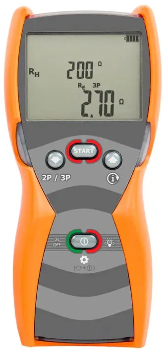
Tellurometers
Applications of Tellurometers
General information on the measurement of earthing resistance and the applications of tellurometers.
In summary, some concepts of earthing measurement are presented.
A good earthing system is necessary to maintain the safety of the people who work or are in contact with the installations, as well as to keep the different equipment of the electrical network in optimum operating conditions.
The different grounding and earth resistivity measurements are intended to guarantee the above, not only under normal operating conditions, but also in the event of any circumstances that may affect the insulation of the lines.
There are two important parameters when designing or maintaining a grounding system: the grounding resistance (measured in ohms, Ω) and the soil resistivity (measured in ohm metres, Ωm).
Resistivity is a fundamental parameter in the design of grounding systems. Resistivity is an intrinsic characteristic of the soil, it is independent of morphology but it does depend on humidity or temperature. It varies throughout the year. The presence of water in the soil does not necessarily imply a low resistivity.
Because soil resistivity varies significantly by soil type and seasonal parameters, the system must be designed for worst-case conditions.
Low resistivity soils are often corrosive as they are rich in moisture and salts, which means that the use of the tellurometer is necessary for periodic monitoring of the grounding system.
In the tellurometer manuals marketed by Amperis, several earth resistance and resistivity measurement systems are described. The connections are shown graphically, which allows them to be intuitively assimilated.
There are also a multitude of didactic articles on the subject that can be of great help. Find out more in our new section Resources - Engineering Articles - Earth Resistance Measurement.


