Summary:
The main factors that must be considered in order to obtain an accurate earth resistance measurement in electrical systems are analysed, especially the geometry of the measuring system, including the minimum distances that must be taken into account.
- Introduction
- Physical nature of earth resistance
- Measurement method
- Fall-of-Potential Method
- Earth resistance measuring equipment
- Figures of the document
Introduction:
The earthing system is an essential element for the electrical safety system and is necessary in order to:
- Allow the protective devices to trip when there is an electrical insulation fault.
- Equalise the potential of the conductive parts that can be accessed simultaneously with the potential of the surrounding earth, in order to prevent people from being exposed to dangerous voltages.
- Allow lightning energy to be dissipated under safe conditions.
- Reduce electromagnetic interference.
Due to the fact that this is a system designed to guarantee safety, its effectiveness should be verified. The dissipation resistance value is the most relevant parameter for testing the quality of an earthing system and its ability to carry out its function. However, the correct measurement of this parameter needs to meet several requirements, which will be analysed in this document.
Physical nature of earth resistance:
Understanding the earth, the natural physical resistance, will help us to assess the conditions that must be met in order to obtain a correct measurement.
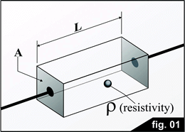
By definition, resistors have two terminals and their resistance is defined as the quotient of the voltage applied across the terminals and the current flowing between them as a consequence of that voltage. The value of the resistance (Eq.1 Equation 1) (R=p.L/A) depends on the type of material (resistivity) and on its physical dimensions (cross-section and length of the resistor), as shown in figure 1.
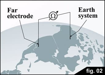
Only one of the terminals is evident in earth resistance. In order to find the second terminal, its definition must be used: Earth Resistance is the resistance that exists between the electrically accessible point of a buried electrode and another point of the earth, which is very far away (Figure 2).
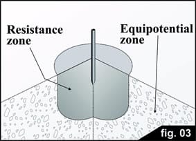
The idea is that, beyond the volume of earth close to a buried electrode through which a current is injected, the whole planet is the equipotential volume related to the current. Any point of the equipotential volume (Figure 3) can be considered as the second electrode of the earth resistance.
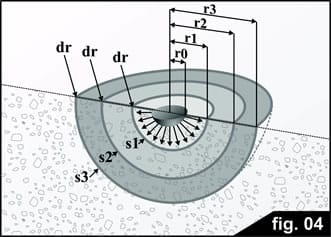
In order to justify the previous statement, we will analyse geometrically the resistance in the area of the buried electrode which, in the following example, is assumed to be hemispherical (Figure 4).
The current that is injected into the earth through the buried electrodes flows out in all directions, with a uniform density (assuming that the soil is electrically homogeneous), and must then pass through the different layers illustrated in figure 4. Each layer offers a resistance to the passage of the current, which is proportional to the soil resistivity and to the layer thickness (length of the resistor in Figure 1), and inversely proportional to the layer area, in accordance with eq.1. The total resistance is then the sum of many small resistances in series. The thickness is arbitrarily defined as being thin enough for both surfaces of the layer to be taken as having the same area (a requirement for applying eq. 1).
In reality, the thickness is infinitesimal and the sum of the resistances is an integral as indicated in eq. 2, where r0 is the radius of the buried hemisphere.
In order to allow an easier physical visualisation of the phenomenon, we can imagine the structure of an onion, formed by a large number of very thin layers, each of which represents one of the resistances in the series.
The important concept to be noted is that, since the soil resistivity was assumed to be homogeneous and the thickness of the layers is the same, the only element that changes (increases), as we move away from the electrode, is the area of the layer. In figure 4, it can be seen that surface S3 is much larger than surface S1. When the surface increases, the resistance decreases in the same proportion and, therefore, the contribution made by the remote layers to the total resistance tends to be negligible.
Calculations for a hemispherical electrode show that in the nearest region, at a distance equivalent to 10 times the radius of the electrode, 90% of the total resistance is concentrated. In other words, the resistance of the layers located outside this area is not significant. And since there is no resistance, there is no potential drop. Good. Consequently, outside the region closest to the electrode (called the resistance area), the whole earth is at the same potential.
Measurement method:
In order to measure the earth resistance, we have to apply a voltage between its terminals that causes a current to flow through it. One of the terminals is the accessible point of the earthing system E. The second, according to the definition, is any other point of the earth, which is really very far away from the first. In order to carry out the measurement, we must drive an auxiliary electrode H in at that point. The second electrode will inevitably have its own earth, resistance and resistance area.
If we look at figure 5, we will see that:
1. Our objective is to measure the earth resistance of electrode E. However, if a conventional resistance measurement between points E and H is carried out by measuring the voltage and the circulating current, the sum of the earth resistance of both electrodes is obtained and not the earth resistance of electrode E. The difference can be very significant since, because of its very condition as an auxiliary electrode, the dimensions of H are very small compared with E, so its contribution to the total resistance can be very significant and the probability of an error is considerable.
2. The concept of "far away", used earlier without further clarification, is now clarified. In fact, the auxiliary electrode H can be considered to be far enough away from the earth resistance system being measured when their respective resistance areas do not overlap. In such a case, the whole volume lying outside the resistance areas is, very approximately, at the same potential, which makes it possible to develop the following measurement method.
Fall-of-Potential Method
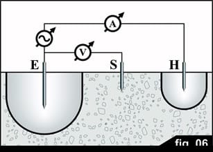
A third electrode S is used in order to avoid the error introduced by the earth resistance of electrode H; the S rod is placed at any point outside the areas of influence of E and H, resulting in a geometry similar to that shown in Figure 6.
This arrangement is known as Fall of Potential and the method is the most commonly used for earth resistance measurement, in which the separation of the resistance areas is obtained with a reasonable degree of distance between the electrodes. The current flows through the earthing system E and the auxiliary electrode H, and the voltage is measured between E and the third electrode S. This voltage is the potential drop that the test current produces across the resistance of the earthing system, Rx, which in this way can be measured without being affected by the earth resistance of rod H.
The 62% rule
Many publications that refer to the Fall-of-Potential Method indicate that, in order to obtain a correct measurement, the three electrodes must be properly aligned and the distance between E and S must be 61.8% of the distance between E and H (Figure 7). This concept comes from a careful mathematical development for the particular case of a hemispherical electrode.
However, this configuration is not easy to apply in real life. The first problem faced is that the geometry of a real earthing system is complex and difficult to equate to a hemisphere in order to determine its centre precisely, from which the distances can be measured with sufficient accuracy. Furthermore, in urban areas it is difficult to find places to position the rods, and it is rare to find available places whose position matches the requirements of the 62% rule (in terms of alignment and distances).
Fortunately, using the same calculations as in the previous method we can derive another geometry, which is easier to apply. Consider joining E and H with the straight line that crosses that segment at its midpoint and that is perpendicular to the said segment. By placing the electrode at any point on the straight line, the measured resistance values lie between 0.85 and 0.95 of the real value of the earth resistance of the electrode. Then, by multiplying the measured value by 1.11 the correct earth resistance value is obtained, with an error of less than ± 5%. It was also observed that as the voltage electrode moves away from the EH segment, the area in which the measured value falls within the indicated tolerance range becomes wider, so that the method becomes more tolerant of changes in the position of the voltage electrode.
Perhaps the error of the proposal may seem too high. In order to assess this point, we will quote Dr Tagg: "... let us bear in mind that a high degree of accuracy is not necessary. Errors of 5-10% [in the earth resistance measurement] can be tolerated ... This is because an earth resistance can vary with changes in weather or temperature and, since such changes can be considerable, there is no point in striving to achieve great accuracy."
Earth resistance measuring equipment
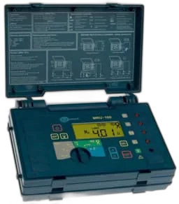
- The earth resistance testers AMRU-100/AMRU-101 are portable instruments that measure earth resistance and soil resistivity by the Wenner method.
- The instrument can measure resistance and resistivity with 2, 3 or 4 electrodes.
- The equipment can be powered by standard type C cells or by rechargeable batteries.
- Measurements can be simplified by using current clamps.
Normal operating conditions:
- Stray currents during AC+DC measurement: max. 24V.
- Test current: max. 225mA.
- Voltage measurement: max. 40V.
- Test current frequency: 128Hz.
- Operating temperature: 0..40°C.
- Supply voltage (for recharging the battery): 230V.
Find out more about earth resistance measurement with Earth Testers in the Earth Testers section