The Nexus® 1500+ is an IEC 61000-4-30 Class A power quality meter and revenue meter that also works as a phasor measurement unit (PMU), streaming IEEE C37.118 synchrophasors at up to 60 frames per second. One device at the substation can bill energy at 0.06% accuracy, record power quality events and feed a wide-area monitoring system.
Grids with a growing share of inverter-based generation are faster and less forgiving than the grids SCADA was designed for. SCADA polls values every few seconds without a common time stamp; a PMU instead reports the magnitude and phase angle of voltages and currents many times per second, all referenced to the same absolute time across the network. Putting this function in the meter already installed at the point of interconnection avoids a separate PMU, its wiring and its panel space.
See the instrument: Nexus 1500 power quality meter, with catalogue and features.
What the Nexus 1500+ PMU reports
A synchrophasor is a phasor (magnitude and angle) estimated at a known instant of absolute time, so phasors from PMUs hundreds of kilometres apart can be compared directly. The Nexus 1500+ streams:
| Group | Channels | In the report |
|---|---|---|
| Individual phasors | VA, VB, VC, IA, IB, IC | Always |
| Symmetrical components | V0, V1, V2, I0, I1, I2 (zero, positive and negative sequence) | Optional |
| Frequency and ROCOF | System frequency and rate of change of frequency | Always (C37.118 frame) |
| Analog | Fundamental W, VA and VAR (total and per phase); displacement power factor (total and per phase) | Optional |
| Digital | The meter's high-speed digital inputs (breaker and relay status) | Optional |
Sending the symmetrical components ready-made saves the phasor data concentrator (PDC) from computing them, and the digital inputs let a breaker operation be time-aligned with the phasor change it caused.
Time synchronisation and reporting rates
Phase angle is only meaningful if the clock is precise: a time error of ±26 µs at 60 Hz, or ±31 µs at 50 Hz, already produces a 0.51° phase error and a 1% total vector error (TVE), the limit in several C37.118 tests. The standard recommends a time source at least ten times better.
For PMU operation the Nexus 1500+ accepts two time sources:
- IRIG-B: unmodulated time code from a GPS-disciplined clock, wired to the meter's IRIG-B port. If the GPS signal is lost, the internal clock (3.5 ppm crystal) takes over at that instant.
- IEEE 1588 PTPv2: precision time over the substation Ethernet network, with the meter as PTP slave and a prioritised list of master clocks for redundancy.
SNTP and line-frequency synchronisation remain available for metering, but not for synchrophasors. Reporting rates follow the nominal frequency:
| Nominal frequency | Frames per second |
|---|---|
| 50 Hz | 10, 25, 50 |
| 60 Hz | 10, 12, 15, 20, 30, 60 |
Frequency is measured over 42.5–69.9 Hz, with 45–65 Hz specified for C37.118. Phasors, frequency and analog values can each be sent as floating point or 16-bit integer (with a multiplier for resolution), and phasors in polar or rectangular form.
Standards compliance: P Class and M Class
With firmware 20 or later and V-Switch™ key 4, 5 or 6, the Nexus 1500+ meets IEEE C37.118.1-2011 and its amendment C37.118.1a-2014 for both performance classes, and communicates to IEEE C37.118.2-2011. The class is chosen in the settings of each installation.
| P Class (protection) | M Class (measurement) | |
|---|---|---|
| Filter window | 2 cycles, triangular | 7 cycles, with band-pass filtering around nominal frequency |
| Response | Fast: one or two phasors can be computed during most faults | Smooth: averages over the fault and does not see fault quantities |
| Typical use | Double- or triple-ended fault location, fast protection-related analysis | Wide-area monitoring, oscillation analysis, state estimation |
The synchrophasor stream uses C37.118.2 only; the meter's IEC 61850 server (V-Switch keys 5 and 6) is not used for PMU data.
Communication and data streaming
The PMU runs over either of the meter's two Ethernet ports (copper or 100Base-FX fibre), one at a time, using IEEE C37.118.2. Commands and data are split between TCP and UDP, so a dropped TCP session does not interrupt the UDP data stream.
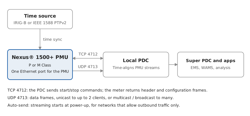
Up to two clients can hold TCP command sessions at once. Ports are configurable, and the Data Stream ID identifies the meter at the PDC. With auto-send enabled, the configuration frame (type 1 or 2) is also re-sent every 1–3600 s (60 s by default), and any configuration change raises the configuration-change flag and restarts the stream.
Applications
- Wide-area situational awareness: operators see voltage, current and frequency at many points on one time base, with dynamic detail SCADA cannot provide; the data can be fed into the Energy Management System (EMS).
- Early warning of instability: growing angle separation or a generator accelerating after a line trip is detected before it escalates.
- Oscillation detection: low-frequency inter-area oscillations are identified, located and classified from the phasor stream.
- Islanding detection and restoration: phase and frequency comparison shows when a distributed generator is feeding an islanded section and helps resynchronise it after a storm or major outage.
- Fault location: P Class phasors captured at the ends of a line support double- or triple-ended fault location.
- Post-event analysis and model validation: time-aligned records explain disturbances and validate the system models utilities use for long-term planning.
- Stress points: locating where the transmission system runs closest to its limits, supporting constraint relief.
One instrument, three roles
The PMU shares hardware with the meter's metrology and power quality engine, so the same CT/VT connection serves billing, power quality and synchrophasors.
| Role | Key capability |
|---|---|
| Revenue metering | 0.06% energy accuracy; Constant Calibration™ self-calibration every 10 s |
| Power quality | IEC 61000-4-30 Class A Ed. 3; IEC 61000-4-15 flicker and IEC 61000-4-7 harmonics Class A; IEC 62586-2 PQI-A; 50 MHz transient capture; EN 50160 reporting; up to 4 GB memory |
| PMU | IEEE C37.118.1-2011/.1a-2014 P and M Class; C37.118.2 streaming; IRIG-B or PTPv2 |
| Communications | Up to six ports including dual Ethernet (RJ45 or 100Base-FX fibre); Modbus, DNP3, IEC 61850 with GOOSE, SNMP |
| Cyber security | Resilient Cyber Security™: 512-bit signed firmware, 128-bit AES for credentials, eight configurable roles, physical sealing switches |
For substations, co-generation sites and independent power producers, this means one panel cut-out, one set of wiring and one cyber-security configuration instead of a meter, a power quality analyser and a standalone PMU.
Setting up the PMU
- Select the time source in General Settings › Time Settings: IRIG-B, or IEEE 1588 PTP (meter as slave, master clock list, delay request rate).
- Enable synchrophasors in General Settings › Communications › Advanced Settings: assign the PMU to Ethernet card 1 or 2, choose P or M Class, ports, UDP destination mode and auto-send.
- Set the nominal frequency, 50 or 60 Hz, which determines the available frame rates.
- Set the PMU parameters in Tools › Phasor Measurement Settings: Data Stream ID (1–65534, unique in the system), data types, polar or rectangular, frame rate, report groups and channel names.
Steps 1 to 3 change the device profile and reset the meter; step 4 can be changed live, without a reset. The same screen shows PMU status, clock sync status and auto-send status, and flags errors such as a missing time source. After a firmware upgrade from V15 to V20, load the factory defaults in that screen before making changes. Configuration is done with CommunicatorPQA® 5.0.68 or later.
The Nexus 1500+ turns a metering point into a standards-compliant synchrophasor source without extra hardware. For anyone who already needs revenue-class metering and Class A power quality at a substation or point of interconnection, the built-in PMU adds wide-area visibility, faster disturbance analysis and better grid models at marginal cost.
Equipment and contact
The Amperis technical department can advise you on choosing a power quality meter and on integrating the PMU into your synchrophasor system.
- Nexus 1500 power quality meter · Nexus Series
- Related article: New power quality meter