Contents:
- Introduction
- Applications
- Resistance
- Principles of Resistance Measurement
- Four-terminal connection methods
- Possible measurement errors
- Choosing the right instrument
- Measuring equipment
Summary:
When it comes to resistance measurement, accuracy is everything. This guide is about obtaining the highest quality measurements possible.
Introduction:
Measuring very large or very small quantities is always difficult, and resistance measurement is no exception. Values above and below 1GΩ present measurement problems. Amperis is a leader in low resistance measurement; we produce a wide range of low resistance ohmmeters and accessories covering most measurement requirements.
This pocket guide provides an overview of low resistance measurement techniques, explains the common causes of error and how to avoid them. We also include useful tables of cable and its characteristics, temperature coefficients and various formulas to make sure you make the best choice when selecting your measuring instrument and measurement technique. We hope this guide proves to be a useful tool for you.
Applications
There are many reasons for measuring the resistance of a material. Here are some of them.
Component manufacturers
Resistors, inductors and chokes; their products must be verified to meet the specified resistance tolerance, for end-of-production-line and quality control testing.
Manufacturers of switches, transmitters and connectors
To verify that the contact resistance is below the limits that must be preset. This can be done at the end of production line testing, ensuring quality control.
Cable manufacturers
They must measure the resistance of the copper cables they produce; a resistance that is too high means that the cable's current carrying capacity is reduced; a resistance that is too low means that the manufacturer is being too generous with the cable diameter, using more copper than needed, which can be very costly.
Installation and maintenance of power cables, switchboards and voltage tap transformers
These require cable joints and switch contacts to have the lowest possible resistance, so as to prevent the joint or contact from overheating; a poor cable joint or a poor switch contact will fail soon because of this heating effect. A preventive maintenance routine based on regular resistance checks will ensure a longer service life.
Manufacturers of electric motors and generators
This is a requirement for determining the maximum temperature reached under full load. To demonstrate this temperature, the temperature coefficient of the copper winding is used. The resistance is first measured with the motor or generator cold, that is, at ambient temperature, then the unit is run at full load for a specified period and the resistance is measured again. The internal temperature of the motor/generator can be established from the change in resistance value. Our ohmmeters are also used to measure the individual coils of a wound motor, to guarantee that there is no short circuit and that each coil is balanced.
The automotive industry
As a requirement, the resistance of welding robot cables must be measured to confirm that the weld quality does not deteriorate, that is, lead battery crimped connectors, airbag squib resistance, wiring harness resistance, and the quality of the crimped connectors on the components.
Fuse manufacturers
For quality control, bonding resistance measurements must be carried out on aircraft and military vehicles; it is necessary to guarantee that all the equipment installed in the aircraft is electrically bonded to the airframe, including the galley equipment. Tanks and other military vehicles have the same requirements.
Producers and users of large electrical currents need to measure the resistance distribution of joints, high voltage busbars, and connectors to electrodes for plating.
Rail utilities
Including tramways and underground railways, for measuring power distribution at cable joints. Covering the resistance of the track joints, since the rails are often used for signalling.
Resistance
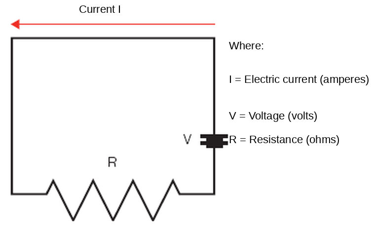
Ohm's Law V = C x R (Volts = Current x Resistance). One Ohm (Ω) is the unit of electrical resistance equal to that of a conductor in which a current of one ampere is produced by a potential of one volt across its terminals. Ohm's Law, named after its discoverer the German physicist Georg Ohm, is one of the most important laws of electricity. It defines the relationship between the three fundamental electrical quantities: current, voltage and resistance. When a voltage is applied to a circuit containing only resistive elements, the current flows according to Ohm's Law, which is shown below.

Principles of Resistance Measurement
Methods
Ammeter - Voltmeter Method
This method goes back to basics. If we use a battery as our voltage source, a voltmeter to measure the voltage and an ammeter to measure the current in the circuit, we can calculate the resistance with reasonable accuracy. Although this method can provide good measurement results, it is not a practical solution for everyday measurement needs.
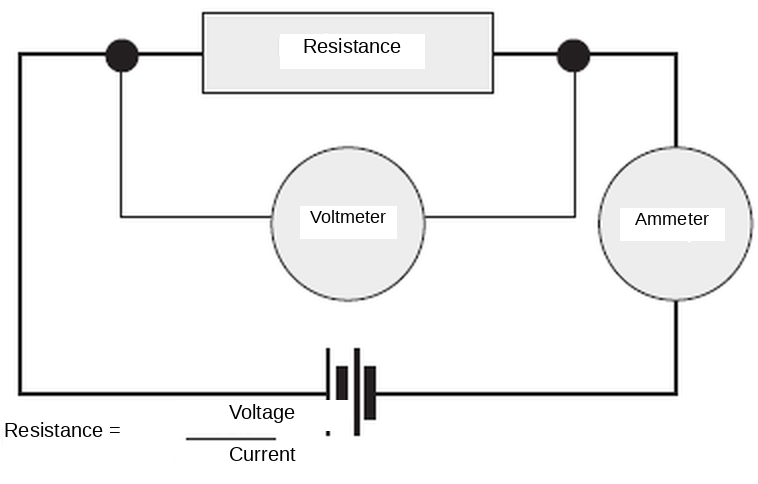

There is a variety of resistance measuring instruments that calculate and display the resistance automatically without the need for user intervention.
These measuring instruments use a two-wire or four-wire measurement technique.
Kelvin Double Bridge
The Kelvin Bridge is a variation of the Wheatstone Bridge that makes it possible to measure low resistances. The measuring range is typically from 1mΩ to 1kΩ with a lowest resolution of 1µΩ. The limitations of the Kelvin Bridge are:
1. It requires manual balancing.
2. A sensitive null detector or galvanometer is required to detect the balance condition.
3. The measuring current must be reasonably high in order to achieve sufficient sensitivity.
The Kelvin Double Bridge has generally been replaced by digital ohmmeters.
DMM – Two-wire Connection
A simple digital multimeter can be used for higher resistance values. They use the 2-wire measurement method, and are only suitable for values above 100Ω and where high accuracy is not required.
When measuring the resistance of a component (Rx), a test current is forced through the component, and the meter measures the voltage at its terminals. The meter then calculates and displays the resulting resistance as a two-wire measurement. It should be noted that the meter senses the voltage at its terminals and not from one end of the component to the other. Consequently, the voltage drop across the connecting leads is also included in the resistance calculation. Good quality test leads will have a resistance of approximately 0.02Ω per metre. In addition to the lead resistance, the resistance of the lead connection will also be included in the measurement and this may be as high as, or even higher in value than, the leads themselves.
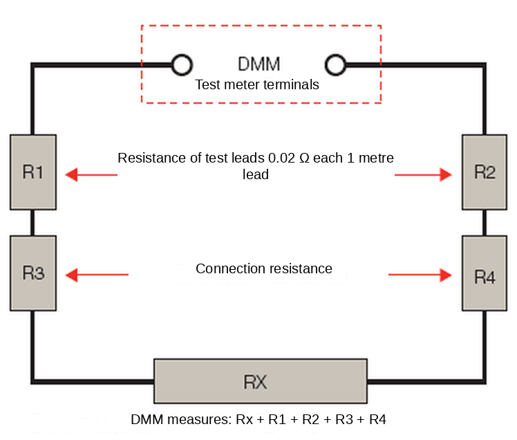
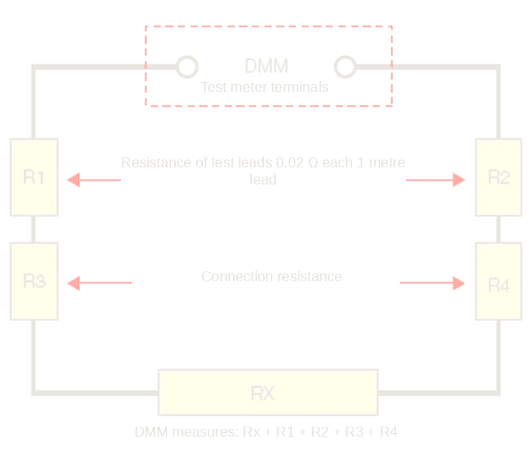
When measuring high resistance values, this additional lead resistance error can be ignored but, as can be seen in the graph above, the error becomes highly significant as the measured value decreases, and totally unacceptable when the measured value is below 10Ω.
TABLE 1
| RX | Test lead resistance R1 + R2 | Connection resistance R3 + R4 | Rx measured at the DMM terminals = Rx + R1 + R2 + R3 + R4 | Error | Error % |
|---|---|---|---|---|---|
| 10000 | 0.04 Ω | 0.04 Ω | 1000.08 Ω | 0.08 Ω | 0.008 |
| 1000 | 0.04 Ω | 0.04 Ω | 100.08 Ω | 0.08 Ω | 0.08 |
| 10 Ω | 0.04 Ω | 0.04 Ω | 10.08 Ω | 0.08 Ω | 0.8 |
| 1 Ω | 0.04 Ω | 0.04 Ω | 1.08 Ω | 0.08 Ω | 8 |
| 100 mΩ | 0.04 Ω | 0.04 Ω | 180 mΩ | 0.08 Ω | 80 |
| 10 mΩ | 0.04 Ω | 0.04 Ω | 90 mΩ | 0.08 Ω | 800 |
| 1 mΩ | 0.04 Ω | 0.04 Ω | 81 mΩ | 0.08 Ω | 8000 |
| 100 µΩ | 0.04 Ω | 0.04 Ω | 80.1 mΩ | 0.08 Ω | 8000 |
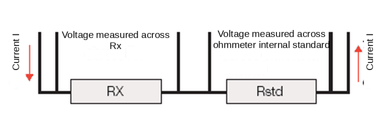
To measure a true DC voltage, resistance ohmmeters typically use the 4-wire measurement. The DC current passes through Rx and through the ohmmeter's internal standard. The voltage across Rx and across the internal standard is then measured, and the ratio of the two readings is used to calculate the resistance. With this method the current only needs to remain stable during the few milliseconds the ohmmeter requires to take the two readings, but it also requires two measuring circuits. The measured voltage is very small and µV measurement sensitivity is also required.

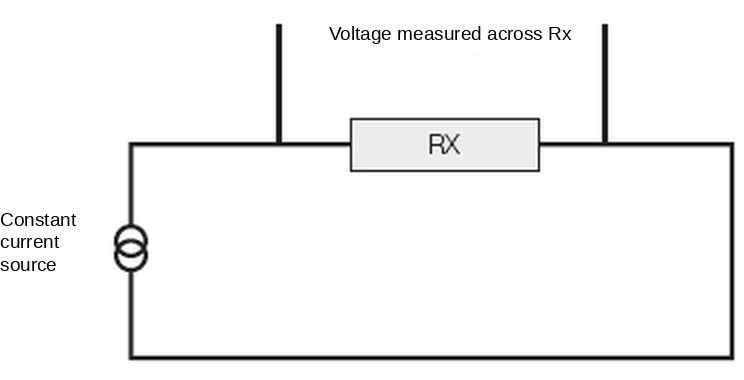
Alternatively, a constant current source is used to pass current through Rx. The voltage drop across Rx is then measured, and the resistance calculated. This method only requires one measuring circuit, but the current generator must be stable under any measurement condition.

Four-wire Connection
The four-wire (Kelvin) measurement method is preferable for resistance values below 100Ω. All Amperis milliohmmeters and micro-ohmmeters use this method. These measurements are made using 4 separate leads. 2 leads carry the current, known as the source leads or current leads, and pass the current through Rx. The other 2 wires, known as the sense or potential leads, are used to sense the voltage drop across Rx. While there is a small current in the sense leads, it will be insignificant and can be ignored. The voltage drop at the ohmmeter's sense terminals is therefore practically equal to the voltage drop across Rx. This measurement method provides accurate and reliable results when measuring resistances below 100Ω.
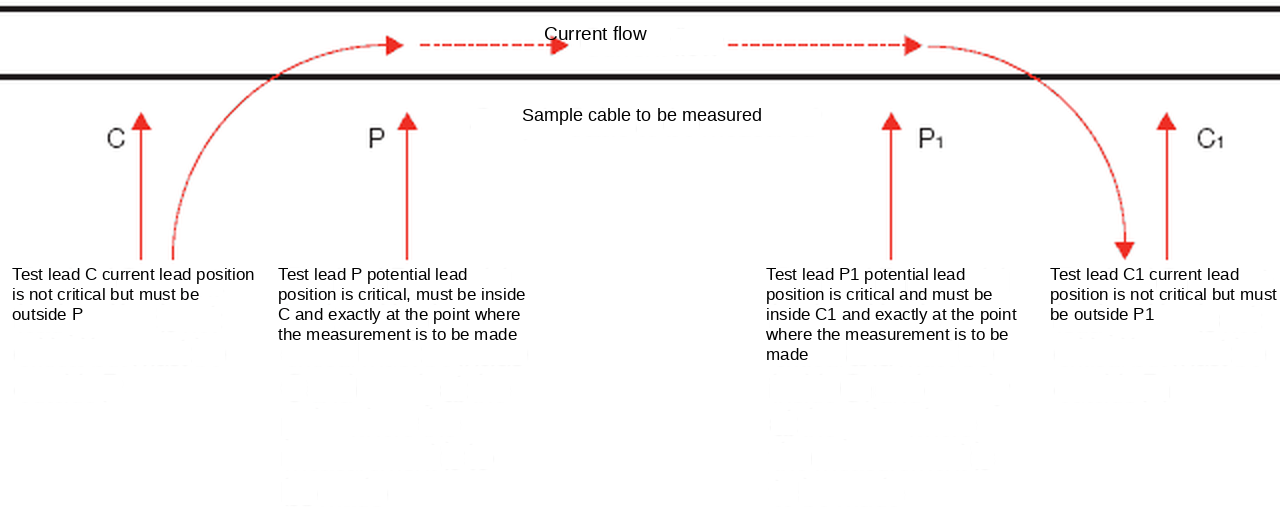
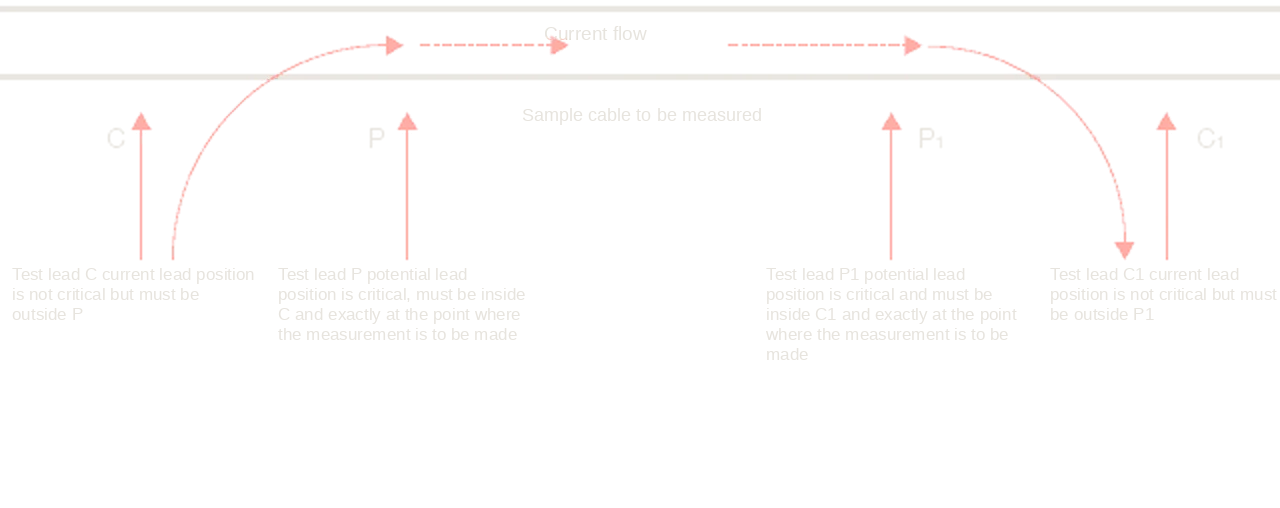
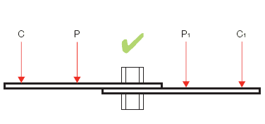
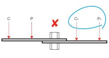
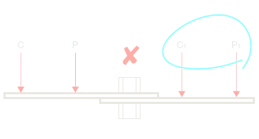
From the measurement point of view, this is the best type of connection, with 4 separate leads; 2 current (C and C1) and 2 potential (P and P1). The current leads must always be placed outside the potential leads, although it does not matter exactly where. The potential leads must be connected exactly between the points you wish to measure. The value obtained from the measurement will be that between the potential points. Although this method provides the best measurement results, it is not very practical. We live in an imperfect world and sometimes it is necessary to compromise; for this, Amperis can offer you several practical measurement solutions.
Four-terminal connection methods
Methods
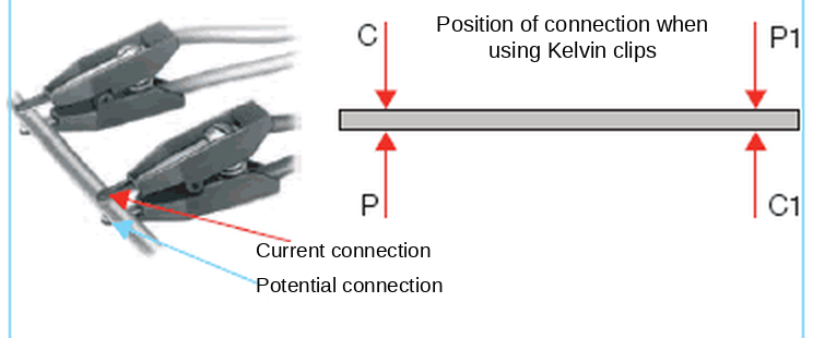
Kelvin Clips
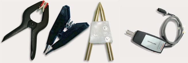
Kelvin clips are similar to crocodile jaws, but with each jaw insulated from the other. The current lead is connected to one of the jaws and the potential lead to the other. Kelvin clips are a very practical solution for making a four-terminal connection to cables, high voltage busbars, plates, etc.
Duplex Handspikes
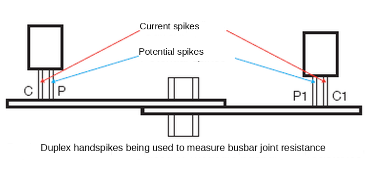
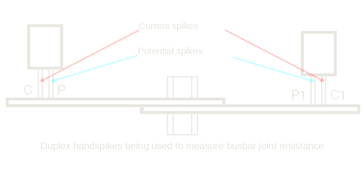
Handspikes provide another practical connection solution, particularly for laminates, high voltage busbars, and wherever access is difficult. The handspikes consist of two probes enclosed in a handle. One probe is the current connection and the other probe is the potential or sense connection.
Stacked Lead Connection
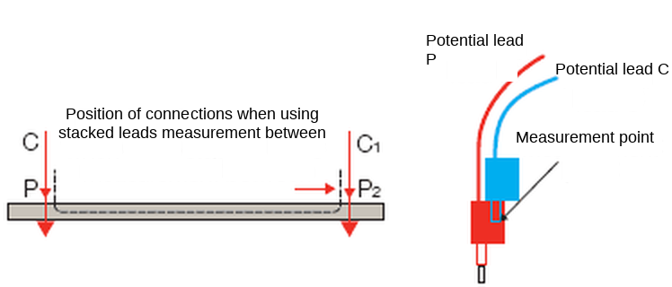
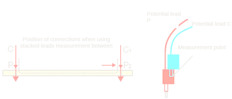
Sometimes the only practical solution for making a connection to Rx is to use stacked leads. The current lead is placed at the end of the potential lead. This method will cause small errors because the measuring point will be where the potential lead connects to the current lead. For difficult samples to measure, this will be the best solution.
Cable Clamps

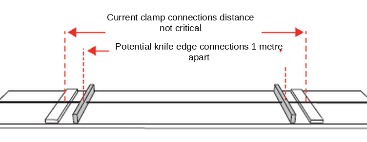
When measuring cables during manufacture, and for the purpose of quality control, it is necessary to maintain consistent measurement conditions. The cable sample length must normally be 1 metre, and to ensure that the length is exactly this, a cable clamp is used. Amperis offers a wide range of clamps that accommodate the most common types of cable. The cable to be measured must be placed in the clamp and the end of the cable is held in the current terminals. The potential connection points are normally in the form of knife-edge contacts, which are exactly 1 metre apart.

Jigs and Fixtures
When measuring other components such as resistors, fuses, switch contacts, screws, etc., the importance of using a test jig to hold the component cannot be emphasised enough. This will guarantee that the measurement conditions, that is, the position of the measuring leads, are the same for each component and will result in consistent, reliable and meaningful measurements. Jigs usually have to be designed specifically to suit your application.
Possible measurement errors
There are several possible causes of error associated with low resistance measurements. The most common ones are described below:
Dirty connections
As with all measurements, it is important to make sure that the device being connected is clean and free from oxide and dirt. High resistance connections will cause reading errors and may prevent measurements. It should also be noted that some coatings and oxides on materials are good insulators. Anodising has a very high resistance and is a classic example. Make sure you clean off the coating at the connection points. Amperis ohmmeters incorporate a lead error warning that will indicate whether the connections are too high in resistance.
Excessively high lead resistance
Although in theory the four-terminal measurement method is not affected by lead length, care must be taken to guarantee that the leads do not have too high a resistance. The potential leads are not critical and can usually be up to 1kΩ without this affecting measurement accuracy, but the current leads are critical. If the current leads have very high resistances, the voltage will drop across them and there will be insufficient voltage across the DUT (Device Under Test) to take an accurate reading. Amperis ohmmeters check that the voltage across the DUT is correct and prevent measurements being taken if the voltage is too low. They also provide a warning display; preventing the reading, ensuring that there are no false measurements. If long measuring leads have to be used, the diameter of the leads must be increased to reduce their resistance.
Measurement noise
As with any type of low voltage measurement, noise can be a problem. Noise is created within the test leads when they are under the influence of a changing magnetic field, or when the leads move within that field. To minimise this effect, the leads should be kept as short as possible, kept short and preferably screened. Amperis knows that there are many constraints on achieving this ideal, and has therefore designed the circuits inside its ohmmeters to minimise and eliminate these effects.
Thermal emf
Thermal emf in the DUT is probably the greatest cause of error in low resistance measurements. First we must understand what we mean by thermal emf, and the way in which it is generated. Thermal emfs are small voltages that are generated when two dissimilar metals are joined, forming what is known as a thermocouple junction. A thermocouple will generate an emf depending on the materials used in the junction and on the temperature difference between the hot, or reference, and the cold junction.
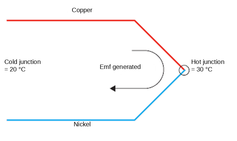

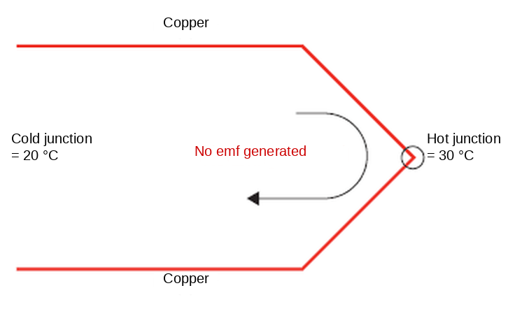
This thermocouple effect will introduce errors into the measurement if no steps are taken to compensate for and eliminate these thermal emfs. Amperis micro-ohmmeters and milliohmmeters eliminate this effect by offering an automatic averaging mode for the measurement, sometimes called switched DC or the averaging method. One measurement is taken with the current flowing in the forward direction, then a second measurement is taken with the current in the opposite direction. The value displayed is the average of these two measurements. Any thermal emf in the measuring system will be added to the first measurement and subtracted from the second measurement; the resulting average eliminates or cancels the thermal emf from the measurement. This method gives the best results for resistive cables, but it is not suitable for inductive samples such as motor or transformer windings. In these cases, the ohmmeter will probably change the direction of the current before the inductance is fully saturated, so a correct measurement value will not be achieved.
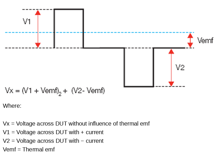
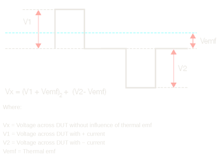
The second method sometimes used consists of connecting the ohmmeter's current terminals together, and with the potential leads connected to the DUT, any thermal emf that may be present can be displayed. This measurement value obtained is stored and subtracted from the following measurement with the current leads and potential leads connected to the DUT in the normal way. All this is done automatically when using Amperis ohmmeters in auto zero mode.Thermal emfs can be relatively high (100mV), so it is important to carefully select the materials used to make the connections. Nickel-plated brass, for example, can produce high emfs when making copper junctions. Kelvin clips are usually made of nickel-plated brass and can produce very high emfs when forming copper junctions with connecting leads.
Improper connection to samples
When making four-wire connections, it is important to place each lead in the appropriate position. The current and potential leads must always be used in pairs, with the current connection outside the potential connection, as shown below.
Wrong test current
The effect that the measuring current has on the DUT must always be taken into account. Devices of small mass or built with materials with a high temperature coefficient, such as copper wire filaments, must be measured with the lowest current available to prevent heating. In these cases, a single current pulse will be appropriate to cause the minimum heating. In the event that the DUT is subject to the influence of thermal emfs, then the switched current method described above is not suitable. Amperis ohmmeters of the PDRM-10A series have selectable currents from 10% to 100% in 1% steps, they also include the single pulse mode and can consequently be configured to suit different applications.
Temperature influences
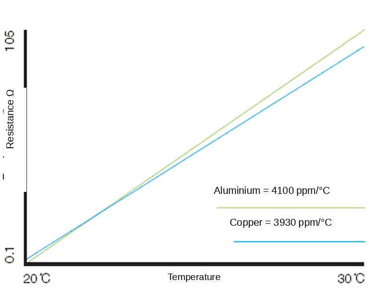
It is important to know that the resistance of most materials will be affected by their temperature. Depending on the accuracy required in the measurement, it may be necessary to control the environment in which that measurement is made, as well as to keep the temperature of that environment stable. This would be the case when the resistance measurement refers to standards, which are measured in laboratories controlled at 20oC or 23oC. For measurements where ambient temperature control is not possible, ATC (automatic temperature compensation) is used. A temperature probe connected to the ohmmeter senses the ambient temperature and the resistance reading is corrected to a reference temperature of 20oC. Two of the most common materials measured are copper and aluminium, and their temperature coefficients are shown in the graph on the right.
The Temperature Coefficient of Copper (near room temperature) is +0.393 % per oC. This means that, if the temperature rises 1oC, the resistance will increase by 0.393%. For Aluminium it is +0.4100 % per oC.
Choosing the right instrument
TABLE 2
| Range | Resolution | Measuring current | Accuracy @ 20 °C ±5 °C, 1 year | Temperature Coefficient / °C | |||
|---|---|---|---|---|---|---|---|
| 60Ω | 10 mΩ | 1 mA | ±(0.15% Rdg + 0.05% FS) | 40 ppm Rdg + 30 ppm FS | |||
| 6 Ω | 1 mΩ | 10 mA | ±(0.15% Rdg + 0.05% FS) | 40 ppm Rdg + 30 ppm FS | |||
| 600 mΩ | 100 μΩ | 100 mA | ±(0.15% Rdg + 0.05% FS) | 40 ppm Rdg + 30 ppm FS | |||
| 60 mΩ | 10 μΩ | 1 A | ±(0.15% Rdg + 0.05% FS) | 40 ppm Rdg + 30 ppm FS | |||
| 6 mΩ | 1 μΩ | 10 A | ±(0.2% Rdg + 0.01% FS) | 40 ppm Rdg + 30 ppm FS | |||
| 600 μΩ | 0.1 μΩ | 10 A | ±(0.2% Rdg + 0.02% FS) | 40 ppm Rdg + 250 ppm FS | |||
Range:
The highest possible reading for that setting.
Resolution:
The smallest number (digit) obtained for that range.
Measuring current:
The nominal current used by the range.
Accuracy:
Measurement uncertainty over the ambient temperature range between 15 and 25oC.
Temperature coefficient:
The possible additional error below the ambient temperature of 15oC and above 25oC.
When selecting the best instrument for your application, the following should be taken into account:
Accuracy can best be described as the measurement uncertainty, which is the closeness of agreement between the result of a value obtained and the true value. It is normally expressed in two parts, that is, a percentage of reading and a percentage of full scale. The accuracy statement must include the applicable temperature range, as well as the time for which the accuracy will remain within the stated limits. Warning: some manufacturers offer a very high accuracy statement, which is only valid for a period of 30 or 90 days. All Amperis ohmmeters specify a full 1-year accuracy.
Resolution is the smallest increment that the measuring instrument can display. It should be noted that in order to achieve high accuracy in a measurement, high resolution is needed, but high resolution in itself does not indicate that the measurement will have high accuracy.
Example: To measure 1Ω with an accuracy of 0.01% (± 0.0001) the measurement must be displayed with a minimum resolution of 100µΩ (1.0001ohms).
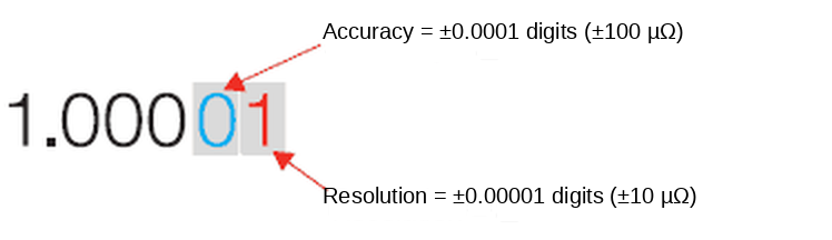

A measurement value can also be calculated with a very high resolution, but with low accuracy, that is, 1Ω calculated to an accuracy of 1%, but a resolution of 100 μΩ, will be displayed as 1.0001Ω. The only significant digits will be 1.0100, the last two digits only show the fluctuations in the measurement values. These fluctuations can be misleading and accentuate the instability of the DUT. An appropriate resolution must be selected to guarantee a comfortable reading of the display.
Measurement scale length
Digital measuring instruments display values on screens that have a counter with a maximum limit, often 1999 (sometimes referred to as a 3Ω digit). This means that the maximum value that can be displayed will be 1999, and the minimum resolution is 1 digit in 1999. For measurements of 1Ω, the display will read 1.000, a resolution of 0.001mΩ. If we want to measure 2Ω, a higher range of 19.99Ω full scale will have to be selected and the value will be displayed as 2.00Ω, with a resolution of 0.01Ω. It can therefore be seen that it is advisable to have a scale length wider than the traditional 1999. Amperis ohmmeters offer scale lengths above 6000, which will make it possible to reach the value of 2.000, with a resolution of 0.001Ω.
Range selection
Range selection can be either manual or automatic. Although automatic range selection can be very useful when the value of Rx is unknown, the measurement takes longer because the instrument has to find the correct range. For measurements on similar samples, it is preferable to select the range manually. In addition to this, the various ranges of the instruments will measure with different currents, which is not suitable for the device under test. When measuring inductive samples, such as motors or transformers, the value obtained increases while the inductance saturates until the final value is reached. Automatic range selection must not be applied in these cases, since when the ranges change the measuring current is interrupted and its magnitude may vary; it will be difficult to obtain a steady reading value.
| Scale length | 1.999 | 19.99 | 2.000 | 20.00 | 3.000 | 30.00 | 4.000 | 40.00 | |
|---|---|---|---|---|---|---|---|---|---|
| Display reading | |||||||||
| Measured values | 1.000 | 1.000 | 1.000 | 1.000 | 1.000 | ||||
| 2.000 | Range | 2.00 | 2.000 | 2.000 | 2.000 | ||||
| 3.000 | Range | 3.00 | Range | 3.00 | 3.000 | 3.000 | |||
| 4.000 | Range | 4.00 | Range | 4.00 | Range | 4.00 | 4.000 | ||