Corona Effect Cameras
Showing 6 of 6
Table of Contents
Download Corona
- Corona is a type of partial discharge in which electrons are emitted into the air.
- The mechanism of electron emission belongs to the realm of physics.
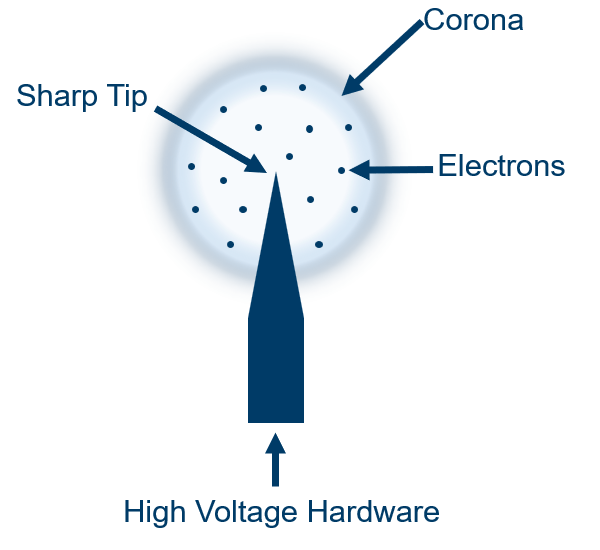
- The whole process begins when cosmic rays ionize the molecules in the air surrounding the high-voltage equipment by deflecting an electron from its orbit.
- View the effect of ionization
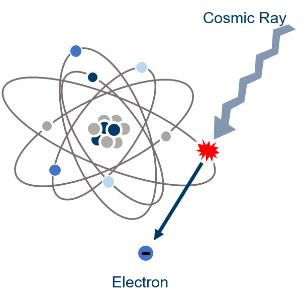
- The free electron released in the process is repelled by the electric field surrounding the hardware during its negative phase.
- And attracted during the positive phase.
- If the repulsive force pushes the electron to a sufficiently high velocity, then it will cause more than one electron to be released during a collision with another air molecule.
- When two or more electrons are released by collision, an avalanche is formed.
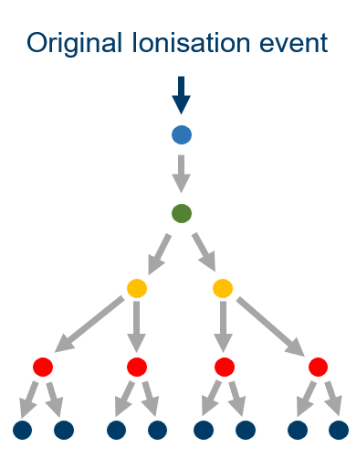
- The avalanche will continue until the electric field has decreased in strength to the point where it does not accelerate the electron to a velocity fast enough to release an electron during a collision.
- In this phase, the collision causes the excitation of the molecule.
- The molecule wants to return to its neutral state.
- To do so, it emits the excess energy in the form of photons of light.
- The frequency of the photons is the same as that of the photons.
- The frequency of the photons depends on the atoms and the bond types of the excited molecule.
In the case of N2 (the main component of the air around us), the frequencies of light emitted are mainly in the UV range, with only 5% above 400 nm, which is considered the lower end of visible blue.
The light spectrum of N2 fluorescence, after having been stretched vertically 1000 times larger.
Corona discharge detection
Corona downloads have several signatures that can be detected:
UV cameras are the best for detecting corona discharges.
The Sun emits ultraviolet light in all bands.
The ozone layer only lets through some frequencies at various volumes.
| Type of UV radiation | Wavelength | Effect | Transmission through Zone O |
| UVA, long wave | 400-315 nm | Skin tanning | 95% |
| UVB, mid-wave range | 315-280 nm | DNA damage | 5% |
| UVС, Shortwave range | 280-100 nm | Cell death | 0% |
Below 280 nm the light from the N2 fluorescence is only visible
Below 280 nm very little light remains, so an image intensifier is used to amplify the light to levels where the camera can perceive it.
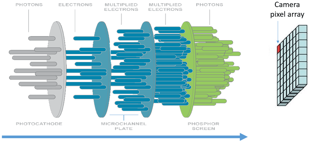
Image intensifiers
Due to the spacing and misalignment of the microchannel plates, some electron scattering occurs during the transition from one plate to the next, resulting in satellite spots around the projection of the discharge site.
CCD operation
When the phosphor screen is impacted by electrons, it glows green.
The green light is detected by the CCD pixels, where it is converted back into electrons.
The CCD has a green light.
The CCD has a maximum charge that it can accept between readings before overflowing.
When a pixel "spills over" it is called blooming."
The blooming of a pixel is called "blooming."
The overflowing electrons make their way to neighboring pixels, increasing their readout value, resulting in a blurry looking image.
When a pixel saturates and "overflows", the additional intensity values that overflow are lost.
Ideally, the ideal is to reduce the gain until the pixel does not saturate, but then lower intensity signals will be lost, which will reduce the camera's sensitivity.
Image Processing - Display
The raw image of the corona is not useful to the inspector, as it contains no structural information that would allow him to identify the physical location of the discharge.
Corona discharge detection
In order to display UVC and visible images in a useful way you have to use 2 types of cameras together with suitable optics.
The detected UV image is superimposed on a visible image to show where the discharge occurs. The UV spot is false-colored to make it observable.
Approach
Once a discharge has been detected, the camera should zoom in to show the operator the physical cause of the discharge.
The camera is zoomed in to show the operator the physical cause of the discharge.
Zooming in is the common term for changing the field of view.
The camera is zoomed in.
Field of view (FOV)
The field of view is the solid angle through which a detector is sensitive to light.
Field of view is the solid angle through which a detector is sensitive to light.
FOV = Field of view
DFOV = Diagonal field of view
HFOV = Horizontal field of view
When a camera is zoomed in, the FOV is reduced.
The black frame is the initial FOV
The green frame shows the zoomed-in FOV.
The green frame shows the zoomed-in FOV.
The green frame shows the zoomed-out FOV.
Optical zoom
Optical zoom is the result of changing the field of view (FOV) of the camera, which is achieved by mechanically changing the relative position of the lens elements.
This is the best type of zoom, since it makes the smallest details visible.
The strength of the zoom is the ability to zoom in and out.
The zoom strength can be expressed as "##x" zoom, but this is not useful since you don't know the initial or final FOV.
So, it is better to indicate the initial and final FOV.
It is better to indicate the initial and final FOV.
i.e.
Digital zoom
Digital zoom magnifies every pixel.
Digital zoom.
- This is the worst type of zoom, since it does not increase the observed detail.
- Digital zoom is generally only applied after cameras have reached their maximum optical zoom.
- The mathematical method used to magnify the pixels has a huge effect on the final result.
Enlargement can be interpolative or non-interpolative. Interpolative gives gradient edges as opposed to non-interpolative, which gives sharp block edges.
- Interpolative enlargement can be used to enlarge the pixels.
Video display
Most modern cameras have image sensors of higher resolution than the camera's display.
Display Zoom - Down Sampling
The video stream can be scaled down to fit the height or width of the screen by down-sampling.
Sensitivity
Camera sensitivity is an important aspect. However, there is no standardized test for the sensitivity of Corona chambers.
Sensitivity.
Sensitivity can be expressed in a variety of ways:
- W/cm2 (watts per square cm): the UV light required for a spot to appear on the camera's screen.
- pC (picoCoulomb): the number of electrons required to generate (by ionization) the UV light necessary for a spot to appear on the camera screen.
- RIV (Radio Influencing Radius): the number of electrons required to generate (by ionization) the UV light necessary for a spot to appear on the camera screen.
- RIV (Radio Influence Voltage): the radio noise generated by the ionization caused by the electrons needed to generate the ultraviolet light necessary for a spot to appear on the camera screen.
Sensitivity units:
- W/cm2 Watt per square cm.
- pC (picoCoulomb) Pico is a unit prefix in the metric system denoting a factor of 10-12 . Coulomb is defined as the amount of electricity carried in one second by a current of one ampere.
- RIV (Radio Influence Voltage) High-frequency voltage, generated by any source of ionization current appearing at the terminals of electrical power apparatus or in power circuits.
Factors affecting the intensity of the discharge and the amount of UV generated:
- The applied voltage
- The charge extracted
- The frequency of repetition of the discharges
- The length of the needle
- The sharpness of the needle
- The needle edge
- The material of the needle
- The surface condition of the needle
- The needle surface condition
- The temperature of the needle
- The conductivity of the ambient air, which depends on air temperature, humidity, pressure and suspended particles
- The velocity of the air flow
- Whether the discharge is seen from the front or not
None of the above are controlled in the corona chamber tests; their effects are also not fully understood.
- The air flow velocity
- The air flow rate
RIV - In theory, actually calculated from pC
IEC 60270:2000 - refers to how pC was measured, not the configuration to generate the discharge. The standard was written before sun shading corona chambers existed and does not address any of the variables that affect the use of corona chambers.
NEMA 107-1987 - addresses how RIV was measured, again it was written long before corona chambers were available.
Given the number of uncontrolled variables (and their effects), it is not appropriate to use a discharge spot as a source of ultraviolet light for camera sensitivity testing.
The use of a device called a blackbody is more appropriate, since few of the variables that affect the discharges affect the blackbody.
The blackbody is used to test the sensitivity of the cameras.
The blackbody is used in physics as a stable source of light over a range of frequencies. The intensity of the light per frequency is easily and precisely controlled by adjusting the temperature of the device.
The only variable is the distance the camera is held from the blackbody aperture.
The only thing to get right is the calculation of the ultraviolet light emitted by the BB through its aperture.
What does the detection interpret?
Most practical users consider a spot in the same location at 50% of the frames per second to be an indication that there is a UV source at that location.
Counting
An expression for the intensity of the discharge was needed to calculate the decay rate of the affected components.
Initially, spot counting was applied.
The only effective result was the decay rate of the affected components.
It was only effective in low-intensity discharges when the camera is out of focus, as overlapping or contacting spots skewed the results.
Initially, spot counting was applied.
Summing intensities proved to be a better approach, as its results were only skewed when the image reached saturation.
The grayscale values of all pixels are summed, and a "blank image" value is subtracted.
This value is then adjusted to the UVc irradiance needed to generate the same intensity.
By changing the sampling area, the intensity of the light received from individual discharges can be measured.
Discharge intensity
To obtain the apparent discharge intensity, a number of factors must be taken into account:
- Distance between the chamber and the discharge source
- The density of the air (air temperature and pressure) and its composition, i.e. gases, humidity, suspended particles, etc.
- The air density (air temperature and pressure) and its composition, i.e. gases, moisture, suspended particles, etc.
- The air flow
- Ionization activity naturally present (depends on altitude)
- The chamber settings
- The type of corona
- The type of crown
- The tension applied
- The viewpoint of the observer
- The point of view of the observer
Inspection camera selector Tell us what installation you inspect, at what distance and what you want to find —hot spots, partial discharges or gas leaks— and get the thermal, ultraviolet, acoustic or gas-imaging camera that covers your specification. You can send us the selection with the technical report attached. Open the selector and find my equipment Close the selector
Undecided between several models? Compare them side by side: Handheld thermal cameras compared · Corona cameras compared