Transformers Testing
Table of Contents
- Types of tests
- Winding resistance measurement
- Kelvin's method (4-wire)
- Measuring the test current
- Measuring on the LV side can be time consuming
- Test current
- IEEE guide for field diagnostic testing of power transformers, regulators, and fluid-filled reactors, IEEE std C57152TM
- Transformer demagnetization
- AC test devices
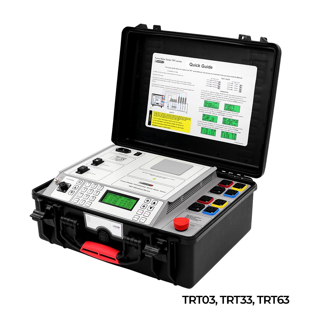
- Turn-ratio measurement
- Excitation current measurement
- Vector group detection
- Phase angle measurement
- SFRA Measurement
Transformer testing instruments
Types of tests
DC tests
- Measurement of winding resistance
- OLTCs analysis
- OLTC vibration testing
- Heat-up test
- Demagnetization process
AC tests
- Measurement of the transformation ratio of power transformers
- Verification of the transformation ratio of instrument transformers
- Measurement of the excitation current
- Phase angle measurement
- Automatic vector group detection
- Vector group detection
- Magnetic equilibrium test
- Magnetic balance test
- Sweep frequency response analysis
Winding resistance measurement
Why is it important?
- Damage to windings and connections
- Malfunctioning of the OLTC contact
- Defined by standards and guidelines
How it is performed
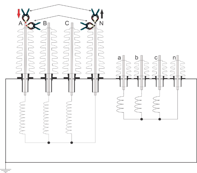
- Inject DC current, measure voltage drop, calculate resistance R = U / I
- Must be done for all phases and each tap position
- Compare with reference measurement, on all phases
Kelvin's method (4-wire)
How is it done?
- Dc current injection, measurement of voltage drop R = U / I
- Time required to charge the windings and stabilize the current
- A larger transformer requires higher currents and more time to saturate
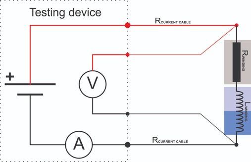
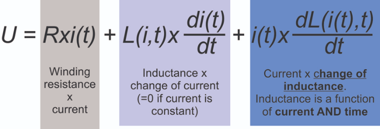
Loading process
- The current flowing through the coils causes a magnetic field that generates an opposing force (EMF) that slows down the charging process
- At the beginning, the EMF is equal to the applied voltage and decreases as the current (Vs/R) increases
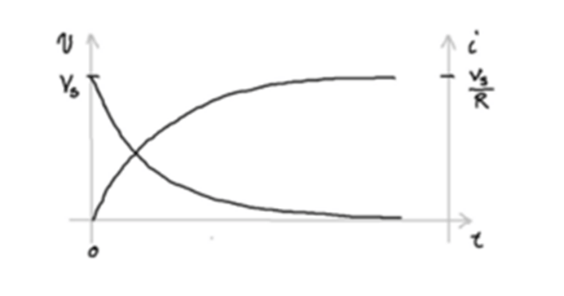
Loading
Loading time
- Volt-seconds needed
- A 100 kV winding at 50 Hz needs 450 Vs
- A 100 kV winding at 60 Hz needs 375 Vs
- Thus, the 50 Hz winding needs 75 s at 6 V
- O ≈8 s at 60 V
- Up to one minute for large transformers
Stabilization process
- Core saturation
- Depends on the time constant L/R
- Eliminates the influence of inductance
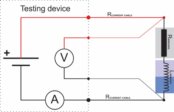
How to saturate the core
- A low current may not saturate the core in a reasonable time
- The stabilization time depends on the time constant L / R
- High current provides better saturation, which leads to less influence of L and ultimately shortens the test time
- Higher magnetomotive force (FMM) = N x I - faster stabilization
- Too high current can heat up the winding (IEC Itest<10%In, IEEE Itest<15%In)
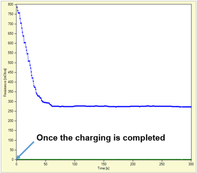
- Higher current => better saturation => less influence of L => shorter time
Too high currents heat up the winding (< 10% of In)

50 A - Test current Cooper heating
Measuring the test current
Test current
Measuring on the LV side can be time consuming
- The LV side can have a very low resistance
- Therefore large L / R time constant
- Especially if the LV windings are delta connected, the current flows through all three phases
- In large units, stabilization can take 15 to 60 minutes per phase
- Sometimes, even 100 A may not be enough to significantly shorten the time
Use the high-voltage winding as an additional aid for faster saturation
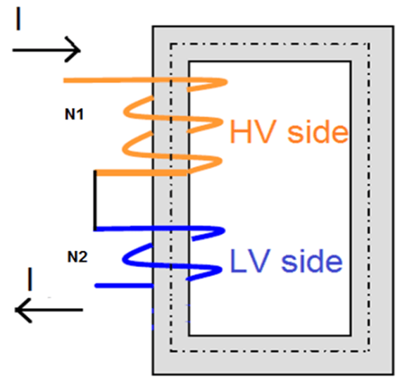
LV winding measurement with HV winding support
- The high voltage side has a much higher number of turns
- More ampere-turns with less current
- Increased MMF = (N1 + N2) ∙ I
- MWF increase = (N1 + N2) ∙ I
- Faster saturation
Test current
How is the test current determined?
- At least 12 x Iex to saturate the core in a reasonable time
- Iex is usually 2-5% of In (rated current)
- Itest = 3% - 6% of In for most power transformers
- Market offerings from 1 A to 100 A
Discharge
Safety
- Inductive energy accumulated in the windings
- Accidental open circuit
IEEE guide for field diagnostic testing of power transformers, regulators, and fluid-filled reactors, IEEE std C57152TM
- In phase-to-phase comparison, the deviation of the resistance value should be less than 2%
- CIGRE Working Group A234 - Guide for the maintenance of transformers
- In comparison between phases, the deviation of the resistance value should be less than 2-3%
- In comparison with the factory acceptance test results, the deviation of the resistance value should be less than 2-3%
What is a "good" result?
Tips from transformer manufacturers
VH deviation between phases - less than 03 - 05%
LV deviation less than 3-5%: more tolerance to error due to other circuit elements and smaller resistance values
The LV deviation between phases - less than 3-5%: more tolerance to error due to other circuit elements and smaller resistance values
The final decision is made based on the technical expertise of the test supervisors and their evaluation of the conditions
The final decision is made based on the technical expertise of the test supervisors and their evaluation of the conditions
Transformer demagnetization
Why is it important?
The remanent magnetism can cause a variety of problems:
- High amplitude inrush current at power transformer start-up
- Malfunction of the protection relays
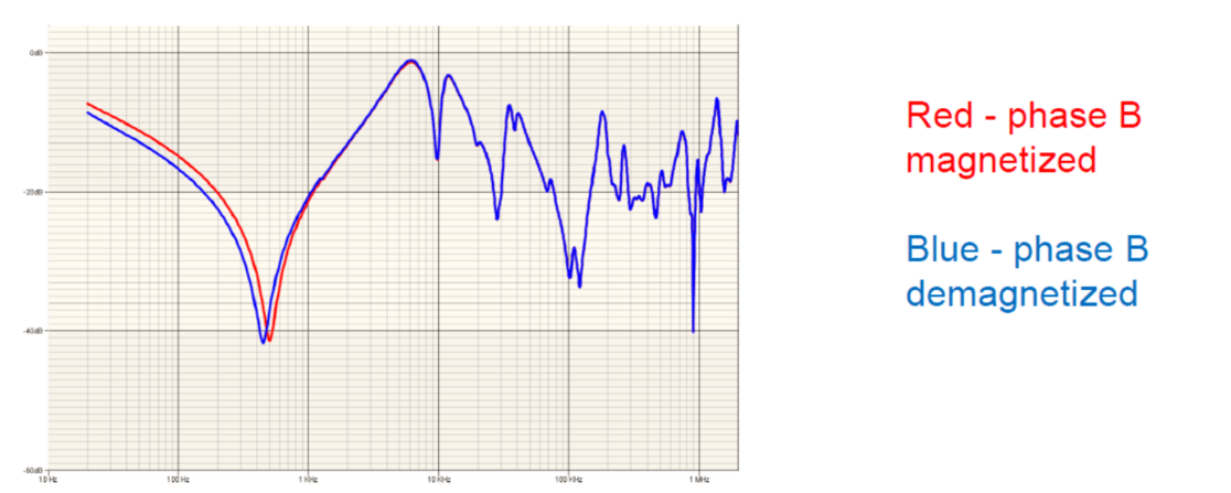
- Erroneous results during electrical measurements on the transformer (FRA test, excitation current measurement, magnetic balance test, erroneous vector group detection)
Causes of transformer magnetization:
- When disconnecting a transformer from service
- Consequence of high fault currents
- When disconnecting a transformer from service
- Testing with direct current
- After a time out of service
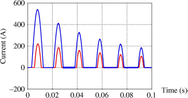
Comparison of maximum inrush current with and without residual flux
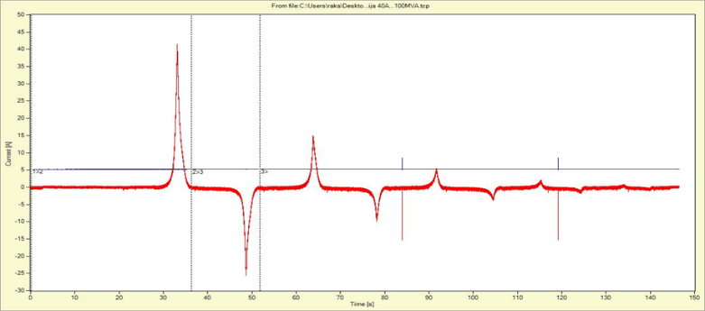
- The user selects the initial current
- At each subsequent step, the current decreases by 40% of the previous value
- Demagnetization ends when a current of 5 mA is reached
How?
- Demagnetization should be performed before AC tests, especially before FRA and excitation current testing, before AVGD, etc
- If the test object is a three-phase (auto)transformer, demagnetization of all 3 phases should be performed
- The initial demagnetization current should be as high as possible If the demagnetization is performed after a DC test on a transformer, such as winding resistance, the initial demagnetization current should have the same value as the current used for the DC test
- Demagnetization should be performed from the side of the transformer that has the neutral point accessible If both the high voltage (HV) and low voltage (LV) sides have/do not have accessible neutral point, demagnetization should be performed from the HV side
When to demagnetize?
- Before AC testing - to avoid bad results due to remanent magnetism
- Before recommissioning a transformer - to avoid high inrush currents and incorrect operation of protective relays
AC test devices
- Turn ratio measurement
- Excitation current measurement
- Phase angle measurement
- Vector group detection
- Magnetic balance test
- SFRA
Turn-ratio measurement
- Most important test
- Detection of defects in the winding/core
- Possible connection errors
- Short-circuits
- Standardized measurement
- The pass/fail criterion for deviations from the turns ratio is ±05 %
- Important for FAT to verify the nameplate
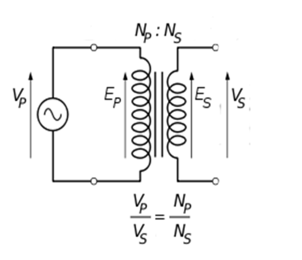
- The ratio is measured by applying a voltage on the high-voltage side and measuring on the low-voltage side
- Phase-to-phase with single-phase voltage
- All phases at once with actual three-phase voltage
- Any type of transformer can be tested, including special transformers, such as phase-shifting transformers, and transformers with non-standard vector group
- Higher voltage: higher accuracy
Excitation current measurement
Why is it important
?
- Short circuit detection
- Laminated core shorts
- Core delaminations
- Delaminations of the core
- Verification of the demagnetization process
How is it performed
?
- The excitation current is the transformer primary no-load current or the magnetizing current (with open secondary) tested at reduced voltage
- The results are compared with the values obtained with the same test voltage values
- The results must follow a specific pattern based on the type of transformer construction
Vector group detection
Why is it important
- Transformer vector group verification
- During/after manufacturing
- During/after repair
- Searching for incorrect connections
How is it done?
- Utilization of a proprietary algorithm and software solution loaded into the TRT
- Fully automatic
Phase angle measurement
Why is it important?
- It can indicate problems in the windings and/or magnetic core
- Measurement of the displacement of transformers with specific vector groups (phase-shifting, rectifier, arc furnace and traction transformers)
- Polarity verification of measuring transformers
How it is performed
- Comparison of the AC voltage(s) applied on the HV side and the AC voltage(s) induced on the LV side
SFRA Measurement
- SFRA measurement
- Frequency response scanning analyzer
- "Fingerprint" method
- Used to evaluate the mechanical integrity of a transformer
- Fingerprint" method
- Core strain/movement
- Core strain/motion
- Faulty grounding
- Faulty grounds
- Short-circuited laminations
- Core deformation/movement
- Faulty grounding
- Coil deformation (axial and radial)
- Winding deformation (axial and radial)
- Short-circuited coils or open windings
- Shifting or deformation of the winding
