Transformer winding ohmmeters
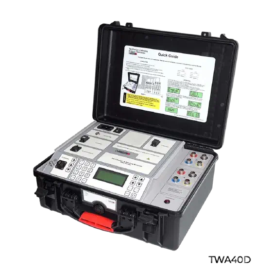
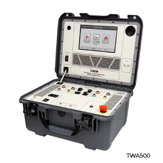
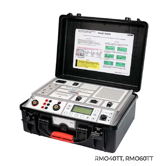
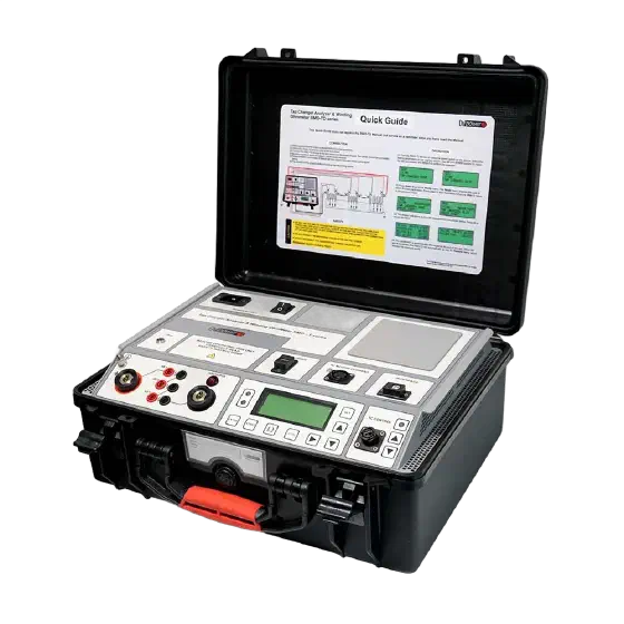
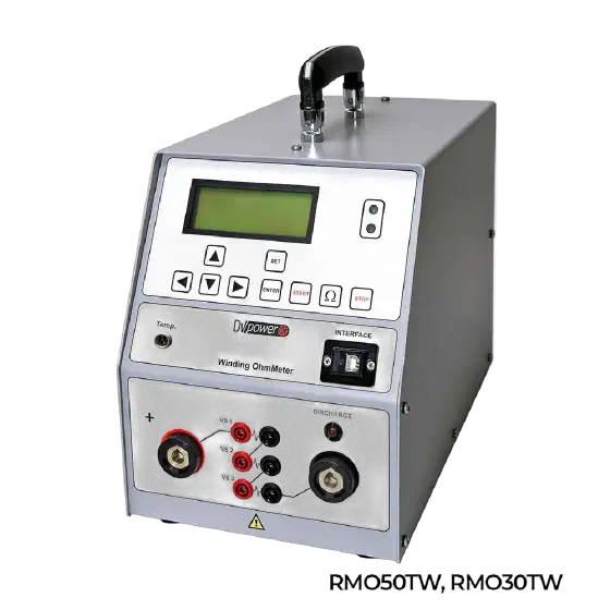
Winding ohmmeters measure the DC resistance of transformer, motor and generator windings with micro-ohm resolution. They uncover shorted turns, loose connections, broken strands and tap-changer trouble — defects an ordinary multimeter cannot see.
What do they measure and how?
The instrument injects a stabilised DC current into the winding, waits for the inductance to saturate and reads the voltage drop through a four-wire (Kelvin) connection that cancels lead resistance. Readings are compared between phases and against factory values: IEC 60076-1 expects only small deviations between phases, so a growing spread points to a defect. After testing, the set demagnetises the core automatically.
How to choose the right unit
- Test current: higher current shortens stabilisation on large transformers; the TWA standard and TWA advanced series cover both needs.
- Channels: measuring two windings at once (RMO-TW series) halves field time.
- Tap-changer testing: RMO-TD series record continuity through the OLTC transition (IEC 60214-1).
- Combined verification: the ROM-TT series add turns-ratio measurement in the same instrument.
Send the transformer rating and vector group to info@amperis.com for guidance.
Applications
- Maintenance and diagnostics of power and distribution transformers.
- Motor and generator checks in industry and renewables.
- Quality control after repairs and rewinds.
Applicable standards
- IEC 60076-1: transformer winding resistance.
- IEC 60214-1: on-load tap-changers.
- IEEE C57.152: field diagnostics of transformers.
Frequently asked questions
Why a four-wire measurement?
A winding can measure just a few milliohms: with two wires, leads and clamps would dominate the reading. The Kelvin connection measures only the drop across the winding itself.
How long does a measurement take?
It depends on inductance: on large transformers the current needs minutes to stabilise. Higher test currents and simultaneous two-winding measurement shorten the job.
Is demagnetising afterwards necessary?
Yes. DC testing magnetises the core, which can cause high inrush at energisation and distort later tests; the range therefore includes automatic demagnetisation.
Resources and contact
Related: transformer ratio meters and the full transformer testing family. Quotations: info@amperis.com · +34 982 20 99 20.
Related calculator
- Correction to reference temperature and phase imbalance IEC 60076-1:2011 · IEEE C57.12.90-2021
- Routine tests on power transformers to IEC 60076-1:2011 IEC 60076-1:2011
Transformer test equipment selector Describe the transformer from its rating plate and tick the tests you need —ratio, winding resistance, tap changer, demagnetisation, SFRA or instrument transformers— and get the instrument or pair of instruments that covers it. You can send us the selection with the technical report attached. Open the selector and find my equipment Close the selector
Undecided between several models? Compare them side by side: Winding resistance testers compared · Turns ratio testers compared · Oil dielectric strength testers compared