Sulphation
Automated charge–discharge regeneration for traction batteries: mechanism, parameters and verification.
Summary. Battery recovery has an image problem. The market is crowded with pulse desulfators and additives sold on the promise that a black box clipped to a terminal will bring a dead battery back to life. Very few are supported by controlled testing.
Genuine capacity recovery, however, is ordinary electrochemistry — and the XD discharger and XMV charger implement it in a way that is fully documented and, more importantly, fully measurable. The manuals do not describe a proprietary waveform. They describe something considerably more useful: a programmable state machine that alternates controlled charge and controlled discharge for a set number of cycles, and logs the ampere-hours recovered at every step.
That distinction is the whole argument of this article. A recovery process you cannot quantify is a claim. A recovery process bracketed by calibrated capacity tests is an engineering result.
1. Why batteries lose capacity
Before deciding whether a battery can be recovered, you have to know what is actually wrong with it. In a lead-acid cell, capacity loss divides into two categories — and only one of them is reversible.
Reversible mechanisms
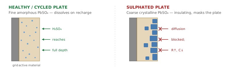
Sulphation. During normal discharge, lead and lead dioxide react with sulphuric acid to deposit lead sulphate (PbSO₄) on both plates. This is not a fault — it is how the battery works. The fault appears when the battery sits partially discharged, is chronically undercharged, or is stored without maintenance. The fine, amorphous PbSO₄ formed during ordinary cycling gradually recrystallises into a coarse, dense, electrically insulating structure. Once crystallised it no longer dissolves at normal charging voltages. The plate area is still physically present, but it is masked. Capacity falls, internal resistance rises, and charge acceptance collapses. We examine the mechanism in more detail in our article on the problem of sulphation.
Acid stratification. In flooded cells the denser acid produced during charging sinks. The lower plate region ends up in concentrated electrolyte and the upper region in something closer to water. The bottom corrodes faster; the top does less work. The battery behaves as though it has lost capacity, but nothing is permanently damaged.
Cell imbalance. In a series string, cells drift apart. The weakest cell reaches its cut-off voltage first and terminates the discharge for the whole string while the remaining cells still hold charge. String capacity is set by the worst cell, not the average.
Irreversible mechanisms
- Active material shedding. Positive-plate paste breaks away and collects at the bottom of the case. Material that has left the plate cannot be returned to it electrically.
- Grid corrosion. The lead grid oxidises over the battery’s life. Once it loses mechanical or electrical integrity, the cell is finished.
- Water loss and dry-out. Electrolyte lost to overcharging or high temperature cannot be replaced in a sealed battery.
- Internal short circuits. Separator failure or dendrite bridging shorts a cell. No charging profile fixes this, and treating a shorted cell is a thermal hazard.
The practical consequence
A sulphated battery is often recoverable. A battery with shed paste, a corroded grid or a shorted cell is not. Any honest recovery programme begins by telling these apart — which is a measurement problem before it is a charging problem. Both manuals reflect this: the XMV troubleshooting tables list battery sulphated and one or more cells are shorted as distinct causes of the same alarm, and both resolve to the same instruction — repair battery — because the charger alone cannot distinguish them.
2. System architecture
The regenerative configuration is two independent cabinets sharing one battery and one control relationship. The XD manual refers to it explicitly as the regenerative system (charger + discharger), and reserves two dedicated parameters for it.
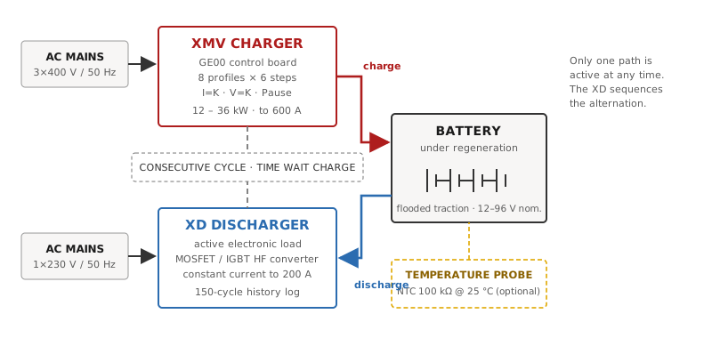
CONSECUTIVE CYCLE and TIME WAIT CHARGE parameters govern the alternation, allowing the pair to run unattended.3. The XD: establishing ground truth
The XD performs a controlled discharge in which current is held constant by a high-frequency DC/DC converter — MOSFET-based in the smaller units, IGBT-based in the larger ones. That architecture matters more than it appears.
A resistive load bank draws current proportional to voltage. As the battery discharges and terminal voltage falls, current falls with it, so the “constant current” test drifts and the ampere-hours calculated depend on how the battery behaved rather than on a fixed test condition. Results are not comparable between batteries, or even between two tests on the same battery. The XD’s active electronic load holds the programmed current from the first second to the last, independently of terminal voltage.
Operation is fully automatic. The operator connects the battery and sets three limits — discharge current, final voltage, and maximum time — plus an optional ampere-hour target. The test terminates on whichever is reached first.
The recommended test conditions are the standard traction test
This is worth spelling out, because it is not obvious from the tables themselves. Every current in the XD manual’s recommended-current table is exactly C₅/5 — the five-hour rate. Every stop voltage in the recommended-stop-voltage table is exactly 1.70 V per cell. Together, those two conventions are the classical capacity test for lead-acid motive-power batteries. Running the XD at its recommended settings therefore produces a figure directly comparable with the manufacturer’s C₅ nameplate rating — not an arbitrary in-house number.
Table 1. Recommended discharge current (XD manual). Every value is C₅/5.
| C₅ (Ah) | Current (A) | C₅ (Ah) | Current (A) | C₅ (Ah) | Current (A) |
|---|---|---|---|---|---|
| 50 | 10 | 300 | 60 | 540 | 108 |
| 60 | 12 | 360 | 72 | 600 | 120 |
| 80 | 16 | 380 | 76 | 700 | 140 |
| 100 | 20 | 400 | 80 | 750 | 150 |
| 120 | 24 | 420 | 84 | 800 | 160 |
| 180 | 36 | 480 | 96 | 900 | 180 |
| 200 | 40 | 500 | 100 | 1000 | 200 |
| 240 | 48 |
Table 2. Recommended stop voltage (XD manual), with the per-cell figure derived. The 1.70 V/cell convention holds across the whole range.
| Nominal (V) | Cells (2 V) | Stop voltage (V) | V/cell |
|---|---|---|---|
| 6 | 3 | 5.1 | 1.700 |
| 12 | 6 | 10.2 | 1.700 |
| 24 | 12 | 20.4 | 1.700 |
| 36 | 18 | 30.6 | 1.700 |
| 48 | 24 | 40.8 | 1.700 |
| 72 | 36 | 61.2 | 1.700 |
| 80 | 40 | 68.0 | 1.700 |
| 96 | 48 | 81.6 | 1.700 |
What the XD records
During the test, pressing SET cycles the display through current (A), capacity discharged (Ah), elapsed time (hours and minute decades) and battery voltage (V). Additional pages show discharge state, battery temperature if the optional probe is fitted, and the history log.
The internal memory holds the last 150 cycles, accessible at any time — including while a discharge is in progress. Each record spans three pages:
Table 3. XD history log record structure.
| Page | Fields | Use |
|---|---|---|
| A | Cycle number (1 = most recent), Vstart, Vstop, start date and time | Identifies the cycle and its open-circuit starting point |
| B | Requested time, requested final voltage, requested Ah, constant current setting | Records the test conditions as programmed — the audit trail proving cycles are comparable |
| C | End date and time, termination code (TT), total time (HH.MM), total capacity returned (AHRET) | The result, and why the test ended |
A 150-cycle buffer is not incidental. A full 20-cycle regeneration campaign on seven batteries fits inside it without overwriting, so an entire workshop batch can be reconstructed from the instrument afterwards.
Scheduling and protection
- Start time window (00:00–23:59, default full day). If a battery is connected outside the window, the XD waits in stand-by until the programmed start time. Once a cycle has begun the window is no longer considered. This exists to move heavy discharge into off-peak hours or overnight.
- Max temperature (45–70 °C, default 60 °C, or disabled). Requires the optional probe — an NTC thermistor of 100 kΩ at 25 °C in a 316 stainless sheath, rated −50 to +90 °C.
- Reverse polarity protection is active: a reverse-connected battery leaves the unit in safe stand-by rather than damaging it.
- Anti-arcing protection is available as an option, requiring a battery connector with auxiliary pins and a wire loop.
- AC blackout shuts the unit down; on restoration it waits for the operator to launch a new cycle rather than resuming automatically.
4. The XMV: the programmable treatment
The XMV is a microprocessor-controlled charger built on the GE00 control board. Its DC output follows programmed charging curves; the base product implements conventional IUIa and IUoU characteristics to DIN 41774, and the unit is certified to UL 1564 (4th Ed., 2015) and CSA C22.2 No. 107.2-01-R2011.
What makes it a recovery instrument rather than simply a large charger is the profile editor.
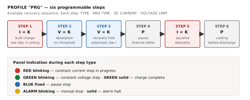
Eight profiles, six steps each
The XMV holds eight programmable profiles, designated A through H. Each profile comprises six independently configurable steps, and for every step the operator sets four things:
- Step type — constant current (I=K), constant voltage (V=K), or pause (P)
- Maximum time for the step
- Output DC current — the constant current in an I=K step, or the minimum current threshold in a V=K step
- Voltage limit — the ceiling in an I=K step, or the regulated value in a V=K step
This is the significant disclosure in the manual. Desulphation on this platform is not an opaque proprietary waveform; it is a six-state sequence the operator builds, documents and repeats. The physics it exploits is well established — holding the battery at controlled elevated voltage and low current for an extended period, so crystallised PbSO₄ is gradually reconverted while controlled gassing agitates the electrolyte and reverses stratification. The engineering constraints are temperature and gassing rate. The value of a programmable six-step machine is that it holds the treatment inside the window where conversion happens and damage does not — and that the profile which worked can be applied identically to the next hundred batteries.
Global limits and access
Table 4. XMV programmable parameters (user and administrator level).
| Parameter | Range | Default | Notes |
|---|---|---|---|
| A–H: charging profiles | 8 profiles × 6 steps | — | Per step: type (I=K / V=K / P), max time, DC current, voltage limit |
| 1: V.MAX max limit | 1.0–3.54 V/cell, 0.01 V steps, or disabled | 3.20 V/cell | Charge terminates with an error if the cell voltage ceiling is reached |
| 2: Temperature max limit | 40–70 °C in 5 °C steps, or disabled | Disabled | Requires a submersible sensor installed in the battery |
| 3: Nominal voltage | 12, 24, 36, 48, 60, 72, 80, 96 V DC | Charger nameplate | Administrator mode only; may need setting after a control-board replacement |
| 4: Nominal current | 200–600 A | Charger nameplate | Administrator mode only |
Two access levels exist, both reached by holding STOP/RE-START for five seconds and then entering a button sequence: four presses of EQ for user programming, four presses of SPECIAL FUNCTION for manufacturer/service programming. Values are edited by holding SPECIAL FUNCTION for three seconds until the cursor blinks.
The control board ships in four communication configurations, which determines whether a regeneration campaign can be logged centrally or only read at the panel:
Table 5. GE00 control board configurations.
| Variant | Designation | External communication |
|---|---|---|
| GE00/E | ECO | None |
| GE00/B | BASIC | RS232, USB |
| GE00/P | PRO | RS232, USB, CANbus #1, special analogue signals |
| GE00/F | FULL | RS232, USB, CANbus #1 and #2, special analogue signals |
Display options are suffixed: 2L for a remote display, 4D for an integrated one — e.g. GE00/P/4D.
Specify the comms variant deliberately
For a regeneration application, the ECO board is a false economy. Without RS232 or USB there is no path off the panel, and the commercial value of the whole process rests on exporting before-and-after data into a certificate. Specify BASIC as a minimum, and PRO or FULL where the charging room is to be supervised centrally.
5. Regeneration mode: the two parameters that matter
The XD manual places two parameters under an explicit heading — special parameters for regenerative system (charger + discharger). These are the mechanism by which recovery becomes an automated process rather than a sequence of manual interventions.
Table 6. XD regeneration parameters.
| Parameter | Range | Default | Function |
|---|---|---|---|
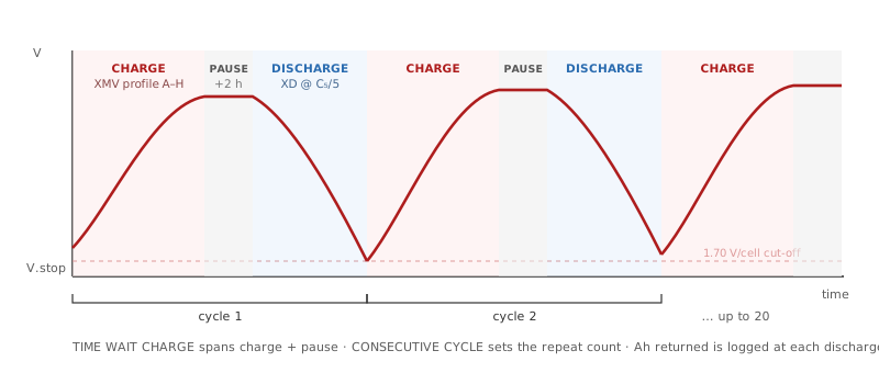
| 4: Consecutive cycle | 1–20, or disabled | Disabled | Number of discharge cycles the XD applies to the same battery in succession. This is the cycle counter for the regeneration campaign. |
| 5: Time wait charge | 1–99 hours, or disabled | Disabled | The window during which the XD yields the battery to the XMV. Throughout this window the XD monitors voltage but will not restart automatically. |
The manual gives the sizing rule for the second parameter directly, and it is worth following exactly: take the maximum charging time and add two hours so the battery has cooled before the next discharge begins.
Worked example
An 80 V, 600 Ah traction battery. Recommended discharge current is C₅/5 = 120 A; recommended stop voltage is 40 cells × 1.70 V = 68.0 V. If the recovery profile needs 14 hours to complete, set TIME WAIT CHARGE = 16 (14 h charge + 2 h cooling). With CONSECUTIVE CYCLE = 5, one full discharge at 120 A takes roughly 5 hours, giving a cycle period near 21 hours and a campaign of approximately 4.4 days running unattended. All five discharges land in the history log, comparable because Page B records the conditions each time.
Why cycling, and why the trend is the evidence
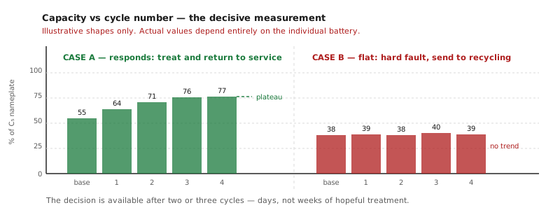
A single treatment rarely extracts the full available gain. Each cycle converts a further fraction of the crystallised sulphate and progressively restores active-material utilisation. But the more important product of cycling is the trend.
6. A worked protocol
The sequence below assumes familiarity with the two underlying operations; if you need the basics first, we have separate guides on how to discharge a battery and how to test your battery.
Table 7. Stage-by-stage protocol.
| Stage | Unit | Settings and purpose |
|---|---|---|
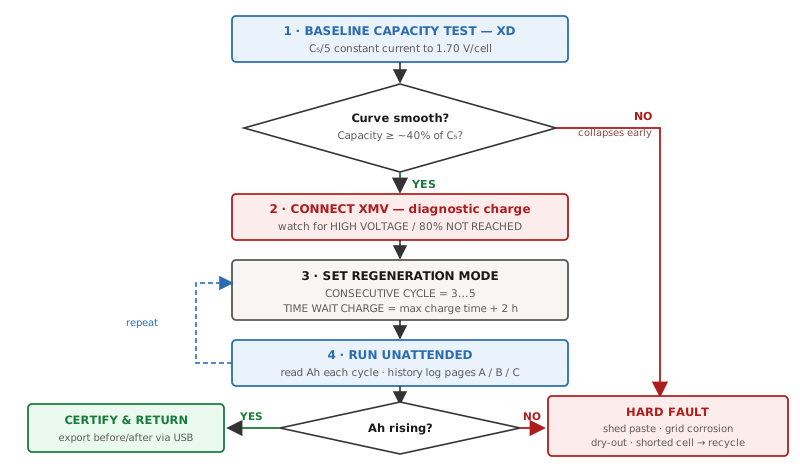
| 1. Baseline capacity test | XD | Current C₅/5, stop voltage 1.70 V/cell, max time set generously. Establishes true Ah and the discharge curve. Reject hard faults here. |
| 2. Diagnostic charge | XMV | Standard profile. Watch for HIGH VOLTAGE or 80% NOT REACHED — both flag sulphation or shorted cells before a full campaign is committed. |
| 3. Configure regeneration | XD + XMV | CONSECUTIVE CYCLE 3–5 for a first campaign; TIME WAIT CHARGE = max charge time + 2 h. Enable MAX TEMPERATURE at 60 °C with the probe fitted. |
| 4. Run | XD + XMV | Unattended. Read Ah returned from the history log after each discharge. |
| 5. Evaluate | — | Rising then plateauing → recoverable ceiling found. Flat from cycle 1 → stop; the fault is not sulphation. |
| 6. Final test and report | XD | Confirmatory discharge under identical conditions. Export the log by USB to produce the certificate. |
7. Reading the diagnostics
Both units surface conditions that are directly useful for triage. The alarm is not merely a fault code; on this platform it is often the first indication of which failure mode is present.
Table 8. Alarm messages and their diagnostic meaning.
| Unit | Display | Documented causes | Diagnostic reading |
|---|---|---|---|
| XMV | CHARGING STOP / HIGH VOLTAGE | Battery sulphated; nominal voltage mismatch; one or more cells shorted | A sulphated battery reaches the voltage ceiling prematurely because its charge acceptance has collapsed. Check every cell voltage and the intercell connections; also verify DC plug and socket torque. |
| XMV | CHARGING STOP / 80% NOT REACHED | The battery has not reached the gassing point within 12 hours. Wrong AC input setting; nominal voltage mismatch; blown output fuse; shorted cells | Rule out the electrical causes first — AC input tap setting and output fuse are cheap to check. What remains points to the battery. |
| XMV | CHARGING STOP / HIGH TEMPERATURE | AC mains too high or low; obstructed ventilation or poor location; battery running hot | The charger applies a cooling pause and then resumes from where it stopped. Repeated triggering during recovery means the profile current is too aggressive — reduce it. |
| XD | EMERGENCY STOP / CURRENT | Difficulty holding the constant-current phase | Battery voltage too low for the discharge current demanded. Reduce the current setting. |
| XD | EMERGENCY STOP / SEE MANUAL | Fuse or power-stage error | Wait 30 minutes for the internal temperature to fall before launching a new cycle. |
| XD | BATTERY TEMPERATURE TOO HIGH | Programmed limit exceeded | The battery appears thermally stressed. Reconsider the discharge current as well as the ambient conditions. |
| XD | ERROR PARAMETER | Incompatible combination of current, Ah, time and final voltage | Re-check all four settings; the requested combination is not physically achievable. |
On "repair battery"
Where the XMV manual's troubleshooting tables list battery sulphated and cells shorted, the prescribed fix in both cases reads simply repair battery. That terseness is itself informative: the charger can detect that something is wrong with the battery but cannot, alone, distinguish reversible sulphation from a dead cell. The XD's capacity trend is what separates them — which is the clearest possible argument for specifying the pair rather than the charger alone.
8. Safety and installation
Hydrogen — the dominant hazard
Charging batteries generate hydrogen, which is explosive in air across an exceptionally wide band — the XD manual gives the flammability limits as 4.1% to 72% hydrogen in air. Spark-retarding vents slow the release rate but escaping hydrogen will still form an explosive atmosphere around a battery if ventilation is poor. Ventilation must be sized for the number of batteries being charged. A regeneration campaign gasses far more than routine charging, over days rather than hours — treat charging-room ventilation as a design input to the installation, not an afterthought.
Never break a live connection
Both manuals are emphatic. Do not disconnect the battery while charge or discharge is in progress: arcing, burnt connector contacts or battery explosion may result. On the XD, hold UP for five seconds to stop; the display shows MANUAL STOP. On the XMV, press STOP/RE-START and wait until the red, green and blue LEDs are no longer blinking — a solid colour means it is safe to disconnect. Ensure the discharger’s digital display is completely off before connecting or disconnecting.
Environmental envelope — the XD is the binding constraint
Table 9. Operating conditions compared. In a combined installation the tighter figure governs.
| Condition | XD discharger | XMV charger | Governing |
|---|---|---|---|
| Operating temperature | 5 to 45 °C | −25 to +40 °C | 5 to 40 °C |
| Storage temperature | 5 to 45 °C | −25 to +55 °C | 5 to 45 °C |
| Relative humidity | < 75% | 0 to 70% | < 70% |
Both units are indoor-rated only. Neither may be exposed to rain, moisture, dust or corrosive substances, and neither should be installed near flammable materials or in the presence of flammable gas.
Clearances
Table 10. Installation clearances from the respective manuals.
| Clearance | XD | XMV |
|---|---|---|
| Sides (ventilation) | 80 cm minimum | 40 cm minimum |
| Front and rear (servicing) | 45 cm minimum | 40 cm minimum |
| Plinth above surrounding floor | ≈ 18 cm (7 in) cement pad | 15 cm cement pad |
Install on non-combustible flooring. Where that is impossible, the XD manual requires a steel floor plate of at least 1.6 mm extending a minimum of 150 mm beyond the cabinet on all sides. Never position either unit directly above or below the battery being worked on — battery gases and fluids will corrode the equipment. Locate them as far from the battery as the DC cables permit, and do not extend the DC cables.
Grounding
The cabinet must be properly grounded, with a grounding conductor of current-carrying capacity at least equal to that of the AC input wires. Where only three-phase power is available, single-phase equipment connects to two wires of the three-phase line only — the equipment grounding conductor must never be connected to the third live wire, which would make the frame live and can cause a fatal shock. Installation and service are for qualified personnel only.
9. Limits, stated plainly
Any supplier who tells you every battery can be recovered is selling something. The honest position:
- Sulphation responds; mechanical damage does not. Shed active material, corroded grids, dried-out sealed cells and internal shorts are terminal.
- Recovery is partial. Realistic outcomes on good candidates run to roughly 70–90% of nameplate, not 100%. The published literature on chemical and inverse-charge recovery of heavily sulphated batteries reports figures around 80% of a fresh unit’s capacity.
- Time matters. A battery sulphated for years is far less recoverable than one sulphated for months; crystal growth is progressive and largely one-way.
- Recovery is not renewal. A recovered battery has still consumed most of its design life. Expect useful additional service, not a second full lifetime — and the service you get depends on the maintenance of industrial batteries that follows.
- Chemistry scope must be confirmed per application. The XMV service manual scopes the charger to flooded lead-acid motive-power batteries, and its conventional profiles follow DIN 41774. The eight-profile, six-step editor and the per-cell voltage ceiling of up to 3.54 V/cell clearly extend beyond that envelope, but any application outside flooded lead-acid should be confirmed with the manufacturer in writing before commitment — for warranty reasons as much as technical ones.
- The measurement is the product. Without a calibrated before-and-after capacity test, “recovery” is an opinion. This is why the XD is not an accessory to the XMV; it is the half of the system that makes the other half credible.
10. Summary specifications
XD discharger / analyser / cycler
| Parameter | XD200/12.EU | XD200/12.US | XD100/12 |
|---|---|---|---|
| Maximum DC power | 20 kW | 20 kW | 20 kW |
| Nominal battery voltage | 12–135 V DC | 12–135 V DC | 12–180 V DC |
| DC output voltage range | 10–140 V DC | 10–140 V DC | 10–200 V DC |
| Maximum DC current | 200 A | 200 A | 100 A |
| AC input | 1 × 230 V AC | 1 × 85–135 V AC | 1 × 230 V AC |
| Cabinet | TD | TD | TD |
Cabinet TD: 335 mm W × 690 mm D × 530 mm H (756 mm with raised keyboard). Power conversion by high-frequency DC/DC converter — MOSFET on smaller units, IGBT on larger. History log 150 cycles. Reverse-polarity protection standard; anti-arcing optional.
XMV multi-voltage charger and conditioner — three-phase range
| Model | Pin max (kVA) | Pout max (kW) | Nominal range | Max current | Cabinet |
|---|---|---|---|---|---|
| XMV.12 | 14 | 12 | 12–180 V | 200 A | TL |
| XMV.15 | 17.5 | 15 | 12–180 V | 250 A | TL |
| XMV.20 | 22.5 | 18 | 12–180 V | 320 A | TP |
| XMV.24 | 28 | 24 | 12–180 V | 400 A | TP |
| XMV.30 | 34 | 30 | 12–180 V | 500 A | TP |
| XMV.36 | 42 | 36 | 12–180 V | 600 A | TP |
Cabinet TL: 483 × 530 × 929 mm (19.0 × 20.9 × 36.6 in). Cabinet TP: 560 × 712 × 1210 mm (22.0 × 28.0 × 47.6 in).
European AC input and protection
Table 11. Mains 400/415 V AC ±10%, three-phase. Breaker type Curve D, fuse type gG.
| Model | Phase current @ 400 V (A) | Pout max (kW) | Pin app. (kVA) | Fuse rating (A) | Mains plug (A) |
|---|---|---|---|---|---|
| XMV.12.EU | 20.2 | 11.5 | 14.0 | 25 | 32 |
| XMV.15.EU | 24.6 | 14.4 | 17.0 | 32 | 32 |
| XMV.20.EU | 32.0 | 18.1 | 22.5 | 40 | 32 |
| XMV.24.EU | 40.5 | 23.0 | 28.0 | 50 | 63 |
| XMV.30.EU | 46.7 | 28.8 | 32.0 | 65 | 63 |
| XMV.36.EU | 60.7 | 34.6 | 42.0 | 65 | 63 |
AC input nominal voltage is set by internal terminal blocks — a screw-type block in some models, a bar-type delta-wye block in others — and on 60 Hz units the auxiliary transformer primary must be moved to match the incoming mains (208, 240, 480 or 600 V). This is done with the charger disconnected from both AC and battery, by a qualified electrician. Certification: UL 1564 4th Ed. 2015, CSA C22.2 No. 107.2-01-R2011; CEC LBSC compliant.
Conclusion
Battery regeneration on this platform is not a black box. It is a documented, parameterised process: a six-step charge profile that holds the battery inside the window where crystallised sulphate reconverts without generating destructive heat or gassing, alternated automatically with a constant-current discharge at the standard C₅/5 rate to a 1.70 V/cell cut-off, repeated up to twenty times, and logged cycle by cycle.
The XMV supplies the treatment. The XD supplies the proof. Neither alone constitutes a recovery programme — the charger can tell you a battery is faulty but not whether the fault is reversible, and that single distinction determines whether a workshop hour is an investment or a write-off.
Together they turn a claim into a number.
Frequently asked questions
How do you know whether a battery is worth recovering?
With a baseline capacity test before any treatment. Discharge at C₅/5 down to 1.70 V per cell with the XD and compare the ampere-hours delivered against the nameplate C₅ rating. A battery that still delivers a usable fraction of its rating and whose fault profile points to sulphation is a candidate; one whose plates have shed material, whose grids are corroded or which has a shorted cell is not, and no charging profile will change that.
How long does a regeneration campaign take?
Days, not hours. Each cycle is one full charge plus a cooling pause plus one full discharge. On an 80 V, 600 Ah battery a charge profile of 14 hours plus 2 hours of cooling plus roughly 5 hours of discharge at 120 A gives a cycle of about 21 hours, so a five-cycle campaign runs for roughly 4.4 days unattended.
How much capacity can realistically be recovered?
On good candidates, roughly 70–90 % of nameplate. The published literature on heavily sulphated batteries reports figures around 80 % of a fresh unit’s capacity. Any supplier promising 100 % on every battery is describing a sales pitch, not a measurement.
Why is a discharger needed if the charger already has desulphation profiles?
Because the charger can detect that something is wrong with the battery but cannot tell you whether the fault is reversible. The XMV troubleshooting tables list battery sulphated and cells shorted as separate causes of the same alarm, and prescribe the same action for both. Only the capacity trend across successive cycles separates the two — and only a calibrated before-and-after test turns a recovery claim into a documented figure.
What does the recovery trend actually tell you?
A series that rises and then plateaus has found the battery’s genuine recoverable ceiling: stop there. A series that stays flat from the first cycle says the fault was never sulphation: stop there too, and the battery goes to recycling rather than back into service. Both answers save workshop hours; only one of them ends in a sale.
What is the most important safety consideration?
Ventilation. Charging batteries release hydrogen, which is flammable in air from 4.1 % to 72 % by volume, and a regeneration campaign gasses far more than routine charging over days rather than hours. Size charging-room ventilation for the number of batteries under treatment, and never break a live DC connection while a charge or discharge is in progress.
Equipment and advice
The XD discharger, analyser and cycler supplies the measurement and the XMV multi-voltage charger and conditioner supplies the treatment; together, in the XD-Combo configuration, they form the automatic cycler this article describes. You can also browse the rest of our battery dischargers and battery chargers and rectifiers, or read our related article on the treatment of sulphated batteries with a charger-discharger-analyser.
Do you have a fleet of traction batteries losing capacity and need to know which of them are worth recovering? Contact our engineers and we will help you specify the equipment and design the test protocol.
Sources
Technical data in this article is taken from the XD user’s manual and from the XMV battery charger service and programming manual (Amperis Products S.L.). Figures 1 and 3–6 are explanatory schematics prepared for this article and are not reproduced from the manuals; the capacity values in Figure 5 are illustrative. Installation, configuration and service must be carried out by qualified personnel in accordance with the manuals and all applicable national and local codes. Specifications subject to change.