Tellurometers: earth resistance & resistivity
Earth resistance testers measure earthing resistance and soil resistivity, the two parameters that decide whether an installation protects people and equipment when insulation fails. The Amperis range covers everything from a quick check of an earth electrode to a full soil survey for designing a substation earthing grid.
What does it measure and how does it work?
Earth resistance (Ω) is measured by injecting current between the electrode and an auxiliary spike and measuring the voltage with a second spike: this is the 3-pole fall-of-potential method, with 2- and 4-pole variants. The clamp and double-clamp methods measure without spikes and without disconnecting the earth, useful on towers and meshed grids, and the impulse method reproduces the behaviour under a lightning strike. Soil resistivity (Ωm) is measured with the 4-spike (Wenner) method: it is a property of the ground that changes with moisture and temperature throughout the year, so earthing must be designed for the worst conditions. Low-resistivity soil is usually rich in moisture and salts, and therefore corrosive, which calls for periodic inspection.
How to choose the right equipment
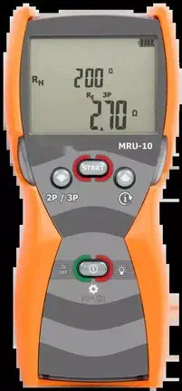
- Basic check: the AMRU-10 measures by 3 and 2 poles up to 9999 Ω, with interference voltages up to 100 V and an IP67 case.
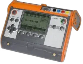
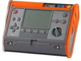
- Design and resistivity: the AMRU-120 adds 4-wire, clamp, double-clamp and soil resistivity.
- Lines and lightning protection: the AMRU-200 also includes the impulse method and leakage current.
- Field traceability: the AMRU-200 GPS stores the position of every measurement.
- Check immunity to stray voltages: in live substations it separates a reliable reading from a wrong one.
Not sure which model? Please get in touch.
Applications
- Earthing grids of substations, power plants and renewable plants
- Earthing of overhead-line towers and lightning protection
- Initial and periodic verification of low-voltage installations
- Resistivity surveys for designing new installations
Applicable standards
- IEC 61557-5 — equipment for measuring resistance to earth
- IEC 60364-6 — verification of low-voltage installations
- IEEE 81 — measuring soil resistivity and ground impedance
- IEEE 80 — safety in substation grounding
Frequently asked questions
Earth resistance or soil resistivity?
Resistance belongs to the installed electrode; resistivity is a property of the soil measured before design. Both are needed: the second to calculate the earthing and the first to verify it.
When should the clamp method be used?
When the earth is part of a system with several electrodes in parallel, such as a line with an overhead earth wire, and you cannot or do not want to disconnect it or drive spikes.
Why measure at different times of year?
Because resistivity changes with moisture and temperature; an earth that passes in winter may fail in midsummer.
Technical resources
Read the article on earth resistance measurement, use the earthing resistance calculator and see the multifunction installation testers. Request a quotation.
Electrical test instrument selector Tell us what you need to measure and on which installation —insulation, earth, loop, RCDs, micro-ohmmeter and other measurements— and get the instrument that covers your specification, with its standard accessories and the ones worth adding. You can send us the selection with the technical report attached. Open the selector and find my equipment Close the selector
Undecided between several models? Compare them side by side: Insulation resistance testers compared · Multifunction installation testers compared · Earth resistance testers compared · Loop impedance testers compared