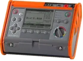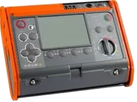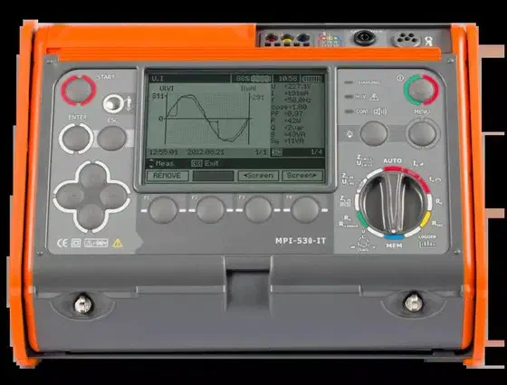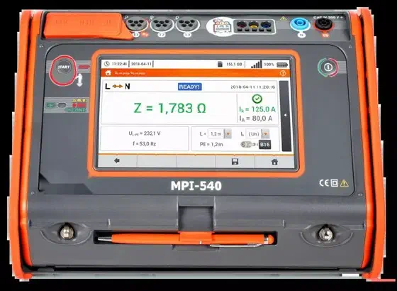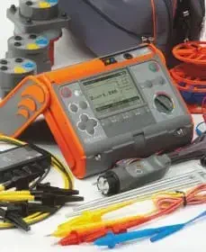
AMPI-520 Multifunction Electrical Installation Meter
Loop, RCD, insulation and earth testing in a single instrument
Verifying protection against electric shock in a low-voltage installation to IEC 61557 calls for a multifunction tester that measures loop impedance, RCDs, insulation, earth and continuity without changing instruments. The AMPI-520 measures the ZL-PE, ZL-N and ZL-L loop from 0.13 to 1999 Ω with ±(5 % m.v. + 3 digits), tests AC, A and B RCDs from 10 to 1000 mA measuring the trip time with ±(2 % m.v. + 2 digits), measures insulation up to 3 GΩ at 1000 V, 3-pole earth from 0.5 to 1999 Ω per IEC 61557-5 and continuity at 200 mA in both polarities.
AMPI-520 key data
- Short-circuit loop: 0.13 to 1999 Ω per IEC 61557 with the 1.2 m lead, 0.01 Ω resolution and ±(5 % m.v. + 3 digits); prospective short-circuit current calculated up to 40 kA and maximum test current of 41.5 A (10 ms) at 415 V.
- No-trip loop: ZL-PE from 0.50 Ω with ±(6 % m.v. + 10 digits) up to 19.99 Ω, without tripping RCDs of IΔn ≥ 30 mA.
- RCDs: AC, A and B types of 10, 30, 100, 300, 500 and 1000 mA; tA with 1 ms resolution and ±(2 % m.v. + 2 digits), up to 300 ms for general and 500 ms for selective RCDs; IA with ±5 % IΔn for sinusoidal and ±10 % IΔn for pulsating and DC current; touch voltage UB from 10 to 99.9 V.
- Insulation: 50, 100, 250, 500 and 1000 V per IEC 61557-2, up to 2.00 GΩ at 500 V and 3.00 GΩ at 1000 V; ±(3 % m.v. + 8 digits) up to 999 MΩ; test current below 2 mA and automatic discharge of the object.
- Earth: 3-pole from 0.5 Ω to 1.99 kΩ at 50 V per IEC 61557-5, ±(2 % m.v. + 4 digits) up to 9.99 Ω, 20 mA sinusoidal at 125 or 150 Hz, auxiliary electrodes up to 50 kΩ and measurement blocked with interference above 24 V.
- Continuity: 0.12 to 400 Ω per IEC 61557-4 with a minimum of 200 mA in both polarities, ±(2 % m.v. + 3 digits) and lead compensation; low-current resistance up to 1999 Ω.
- Instrument: 4 LR14 batteries or a 4.8 V 4.2 Ah Ni-MH pack for more than 3000 loop or RCD measurements, 990-cell memory (57,500 results), USB, IP54, CAT IV 300 V (CAT III 600 V), 288 × 223 × 75 mm and 2.2 kg.
Advantages
Loop measurement without tripping the RCD
It automatically calculates the short-circuit loop impedance with a resolution of 0.01 Ω without the need to trip RCDs of 30 mA or above, and detects the phase-to-neutral and phase-to-phase voltage during the measurement itself.
Full RCD testing
It checks general and selective protections of type AC, A and B, for rated differential currents of 10, 30, 100, 300, 500 and 1000 mA, with a trip-time test (mode tA) and a tripping-current test (IA) using sine-wave, unidirectional half-period and DC test currents.
Insulation up to 3 GΩ
It applies 250 V, 500 V or 1000 V test voltage, with automatic discharge once the measurement ends and acoustic signals at 5 s intervals to plot the insulation characteristic curve.
One instrument for several measurements
Earth resistance and bidirectional continuity of the protective conductor are complemented by the phase sequence check and the measurement of voltage, frequency, active, reactive and apparent power and power factor.
Applications
- Periodic diagnostic testing of electrical installations under IEC 61557.
- Certification of installations for authorised electrical installers.
- Verification of general and selective RCDs before commissioning.
- Earth and insulation resistance measurement for preventive maintenance.
About the product
The instrument runs on LR14 alkaline batteries (4 units) or an optional Ni-MH battery pack, has a battery-charge indicator and an auto shut-off function, and stores the measurements in a memory divided into 10 banks of 99 records each. An optional adapter allows automatic measurement of all resistances on 3, 4 or 5-wire cables, and a UNI-Schuko connector makes automatic loop and insulation measurement easier; a further adapter extends the loop test to three-phase networks. The USB interface allows the records to be downloaded to a PC.
It is supplied with a UNI-Schuko probe, test leads and pointed probes, alligator clips, an earth contact probe, a carrying case and a calibration certificate; optional accessories include longer leads, three-phase plug adapters, a current clamp, a Ni-MH battery pack and the software for treating the records on a PC.
Technical specifications
| Loop Z L-PE, Z L-N, Z L-L | 0.13...1999.9 Ω, ±(5 % m.v. + 3 digits) |
| RCD testing | 10-1000 mA, types AC, A and B; tA and IA tests |
| Insulation | 250/500/1000 V; up to 3 GΩ |
| Earth RE | 0.5...1999 Ω, IEC 61557-5 |
| PE continuity | 0.00...400 Ω, ±200 mA |
| Category / protection | CAT IV 300 V; IP54 |
| Power supply | LR14 batteries (4 units) or optional Ni-MH pack |
| Standards | IEC 61557, -2, -5; EN 61010-1; EN 60529 |
| RCD accuracy | tA: ±(2 % m.v. + 2 digits); IA: ±5 % IΔn (sinusoidal), ±10 % IΔn (pulsating and DC) |
| Insulation and earth accuracy | RISO: ±(3 % m.v. + 8 digits) up to 999 MΩ; RE: ±(2 % m.v. + 4 digits) up to 9.99 Ω |
| Insulation test voltages | 50, 100, 250, 500 and 1000 V; current < 2 mA |
Frequently asked questions
Which multifunction tester is suitable for verifying low-voltage installations to IEC 61557?
One that covers loop, RCDs, insulation, earth and continuity in the same instrument. The AMPI-520 measures the loop from 0.13 to 1999 Ω with ±(5 % m.v. + 3 digits), AC, A and B RCDs from 10 to 1000 mA, insulation up to 3 GΩ, earth from 0.5 to 1999 Ω per IEC 61557-5 and continuity at 200 mA per IEC 61557-4.
How accurately does the AMPI-520 measure RCD trip time?
±(2 % m.v. + 2 digits) with 1 ms resolution (±(2 % m.v. + 3 digits) for 10 mA at 0.5 IΔn); at 0.5 and 1 IΔn the range reaches 300 ms for general RCDs and 500 ms for selective ones, and the trip current IA is measured with ±5 % IΔn for sinusoidal current.
Can it measure the loop without tripping the RCD?
Yes. The measurement with 0.01 Ω resolution does not trip RCDs of 30 mA or above.
Which RCD types does it test?
General and selective RCDs of type AC, A and B, at the six rated currents from 10 to 1000 mA.
Up to what resistance does it measure insulation?
Up to 3 GΩ, applying a 250 V, 500 V or 1000 V test voltage.
How are the stored records treated?
They are downloaded to a PC over USB and organised with dedicated software for the documentation of the electrical measurements.